The Compere Project manages everything, so Actor also includes all its elements there too. Inputs, Outputs, Timelines, and all associated devices (hardware running Compere as a performer) and interfaces will be added as an Actor-based system is constructed.
Every device in the Project panel Devices tab can be regarded as a node that can be added to the Nodes panel for interconnections and processes, and can be addressed via external control. This makes media servers and connections configurable.
Project Devices
Project devices are the hardware elements (internal devices) available to join a Project Group to perform a role: Juggler, Actor, or Conjurer. All devices connected in the project network show here in the panel, and when selected, their connections are exposed: GPUs, ST 2110 inputs and outputs, audio, GPIOs, video channels and so on.
Video
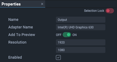
GPUs are selectable under the project tree ‘devices’ tab under ‘Outputs’.
Audio
Audio playback is configured by selecting the local audio device under the project tree ‘devices’ tab under ‘Devices’, and editing the properties. This includes enabling audio with that device.
➢see Audio Playback
Project Tree
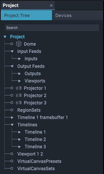
As Projects and timelines are constructed, all the elements that comprise a show from inputs through to media on audio visual outputs is assembled as project contents. The structure is useful to understand, though mostly there are easier points of access to address the properties of particular contents.
Video: Input Feeds section
All video inputs are listed together, whether external streams or in-project timelines. When a timeline or other input is brought from the Project Tree into the Input Feeds panel, it creates a video framebuffer listed under Inputs. These framebuffers have the pixel resolutions presented as a whole by each timeline. Inputs, including timeline framebuffers, can be renamed and are listed alphabetically.
Other direct inputs such as cameras, ST 2110 streams and NDI inputs will be listed in the project tree in their own right. Any input brought in as a Node becomes available to the Input Feeds panel.
Note that an NDI feed from a named source can be utilised solely as an internal live tracker within Compere UI, or as a timeline resource. In the former case, it is a direct internal feed, in the latter case, it is displayed as any other timeline resource but is also available to place for internal tracking. To display NDI feeds on a model in the Visualise panel, make sure the Actor output source of the feed (under ‘Devices’) has the property ‘Add to Preview’ enabled:

The role of viewports
Pixels from inputs are collected selectively for processing as streams by applying viewports over them. These are ‘children’ of input ‘parents’. Viewport pixel areas can be bigger than an input, or cover only part. Several viewports can be applied to a single input, reducing the bandwidth of each stream, or a single viewport applied over the whole input to cover all or a selected area of outputs. Viewports belong to inputs as children.
➢see Input Feeds Panel
Video: Output Feeds section
When device outputs are introduced from the Project panel (under Devices) into the Output Feeds panel, to assemble an array of outputs, they are added here to the project as output areas. Dimensions are inherited from the EDIDs of the devices, and relative positions are set by the user. They can be renamed for easier identification, and arranged in whatever matrix arrangement is required.
Viewports, the video streams selected from the timeline input framebuffers, are replicated in the output feed manager, so initially appear sequentially as ‘Viewport1, 2, 3’ and so on in the same way as for the input feeds. Viewports can be renamed, can be resized or scaled, and the feed rotated in 90 degree increments within the viewport.
As in the Input Feeds panel, output viewports can be positioned anywhere over a display area of multiple outputs, so are at the same hierarchical level as outputs. The difference is that the viewports are not attached to any particular output area.
Other direct outputs such as ST 2110 outputs will be listed in the project tree in their own right. Any output brought in as a Node becomes available to the Output Feeds panel.
➢see Output Feeds Panel
Timelines section
Timelines are listed together in the order they are added. Each timeline has nested layers:
Timeline Layers are added when assets are placed on a timeline. A timeline layer can only contain assets of one type (audio, image, movie etc.).
Timeline Groups are added to a timeline when multiple assets on a timeline are made into a selection group (select assets on a timeline, right-click and ‘Add selections to group’). Timeline Groups can be renamed.
Keyframe sets added to a layer, comprise a set of points along the timeline with associated properties of any entity, so that they are changed smoothly between the points. The entity is listed in the layer resource set of the same layer. Keyframes, for example may be used to change size, position, opacity of a viewport, a layer, a timeline, a window, or a movable object, lens characteristic etc.
Layer Resource Sets are all the assets that have been added into a layer.
Timeline Markers run through all layers are added at the playhead position but can be dragged or assigned to any position to trigger an action or control. They mark a position and can be used for stop and rewind.
➢see Timelines
Non-timeline entities
Other entities in the project, such as cameras, NDI receivers, projectors or object models, and audio DSPs, are added to the project as root-level entries. Connections between devices and other content are made in panels such as Nodes or Visualise.
