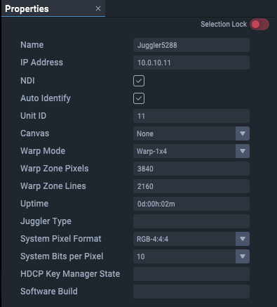
In the Project panel, under ‘Devices’, select the part of a Juggler for which you want to see the properties. Some of these properties relate to the unit as a whole.
Select an individual Juggler name in the Project panel for its module level properties.

Note the Selection lock top right. Since you can open multiple Properties panels simultaneously it can be useful to retain sight of properties for one element whilst editing those of another. Switch the lock on to keep these properties active while looking at another set of properties.
Name
By default, the Juggler serial number. Rename, perhaps to reflect real-world tagging or purpose in your project.
IP Address
This unit's IPv4 Address (see Network Configuration).
NDI
Check this to introduce NDI confidence monitoring on Juggler I/O connectors and in the Canvas assembly panel. In the latter, all video can separately be switched off.
Auto Identify
When enabled, the outputs from this Juggler will throw a sequence of RGB colours in turn onto an output to identify it, when an output is assigned to a video channel.
Unit ID
Last octet digits of the Juggler module’s IP address, to provide an identifier within the project group. Unit Id is appended to connector identifiers and their type, e.g. when one Juggler AV connection is receiving from an AV connection on another.
Canvas
Select from list of Canvas names created (there may be only 1). Applies to all video channels of the Juggler (same setting as in the Juggler title bar in the Nodes panel).
Warp Mode (warp and blend firmware only)
Depending on the firmware of the Juggler, the unit may be configured for warp and blend rather than flat display windowing. For warp and blend units there are 3 warp modes: 1 × 4, 2 × 2, 4 × 1 (this X-Y orientation setting has to match supplied warp files). Warp Mode describes how the four input channels into the particular Juggler unit should be interpreted. Defining the arrangement of the source channels allows an output to span across multiple inputs.
Warp Zone Pixels / Warp Zone Lines (warp and blend firmware only)
Provides a mechanism to override the size of the input Warp Zones (i.e. the video feed into each Video Channel). If this is left at zero then Juggler will use the incoming video resolution of Video Channel:1 to determine the correct size – however, this can cause issues if the video is not present when the warp is being calculated.
Note: All Warp Zones must be the same size.
Warped Test Patterns (warp and blend firmware only)
Select from: Grid, None, X-Ramp, Y-Ramp
Uptime
Total time continuous running of the Juggler FPGA since last restart.
System Pixel Format
Select as appropriate, e.g. RGB 4:4:4.
System Bits Per Pixel
Select as appropriate 8- or 10-bit.
HDCP Key Manager State
For users of HDCP (content protection). See also Video Interface Properties.
Values:
Initialising
Read Key File
Failed to Read Key File
Key File Decrypted
Failed To Decrypt Key File
Keys Written to Flash
Failed to write keys to flash
Read Keys From Flash
Failed to read keys from flash
Ready
Disabled
Properties of the component parts of a Juggler
➢GPIO
Properties of the connections and channels are described in context.
You can select the same feature in more than one Juggler, and edit shared properties as one. See Project Panel.