In order to see the complete Compere-supported system, switch on all networked devices, inputs, outputs and displays.
Open Compere on a Control PC for the first time, and you will be in a new empty Project. We shall learn more about Compere Projects later; for now, get to know how Compere is put together.
This guide will take you through the default Juggler workspace for a project. If not in the default workspace, select ‘Juggler’ from the workspace selector:

An alternative default workspace is ‘Visualise’, which introduces a 3D scene assembly panel for modelling a 3D space, with interactive projectors, displays and surfaces to configure. This is described separately. |
Workspaces
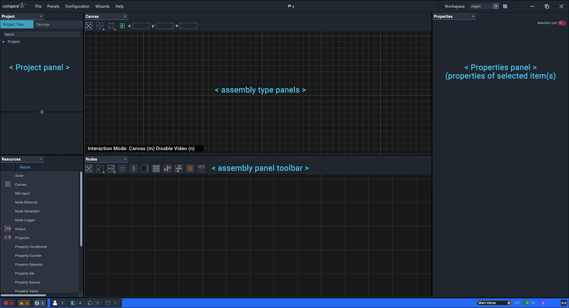
The Juggler workspace is just a default arrangement of panels in the Compere main window. Note the default Nodes and Canvas assembly panels, and the sidebar panels. You may want to maximise the screen:
The initial default ‘Juggler’ workspace comprises:
•the main (top) menu area
•the ‘Project’ panel (default: upper left), listing all configurable elements, tabbed as ‘Project Tree’ or as ‘Devices’ (Actor, Conjurer servers or Jugglers)
•the ‘Properties’ panel (default: right) for any selected element(s) in a Project.
•the ‘Resources’ panel (default: lower left), showing a range of asset types that can be added to a Project
•a grid ‘assembly type panel’ with a tab marked ‘Canvas’
•a grid ‘assembly type panel’ with a tab marked ‘Nodes’
•a coloured status bar.
If any of the panels is not present (you can close any element) they can be reopened from the top menu item Panels, or by restoring the default view, size and screen location from Panels > Reset UI. If you rearrange the parts as you prefer for different tasks, you can save and retrieve custom Layouts.
|
Once you have saved a workspace, do not press Reset UI because this will delete your workspace and revert to a default. |
Project panel
The Project panel is a branching structure of every elements and detail in a Compere project. These can be dragged into assembly panels as appropriate, examined for properties and address through external control.
The two tabs reflect everything being used in the project, and the devices that run it (Jugglers, Actors, Conjurers).
When you start Compere for the first time, you will find a new empty Project. Once saved, projects are held as extensive xml files, by default stored on the server in C:\Users\[username]\AppData\Local\Compere\Projects, with the extension .prj.
The Project is where you will assemble everything required to ‘set the stage’. Your devices will appear in here when present in the same project group, as will your canvases, outputs, projectors, 3D models and any other component as you add them in.
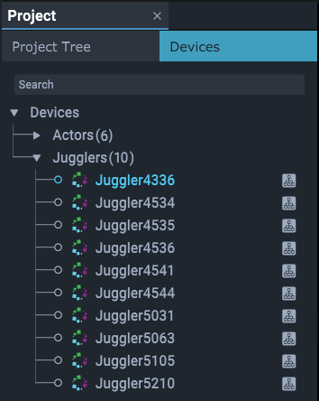
When you join a network with the Compere UI on a device, all Devices available on that network will be represented in the Project panel on the left side. They will be in a group under a title that shows how many are present.
This is just the list of what is available. Each can be named, and examined for the properties of all its connections.
From here, you will select and drag Juggler names into Nodes panel to further configure and connect them (see Nodes: Connecting Juggler Systems). Only Jugglers in the same project group can be added to the Nodes panel, and those that have then been added are identified by an icon to their right (as shown above).
When a Juggler is physically connected to display outputs via DisplayPort or HDMI, and is switched on, a test pattern can be displayed. Until media inputs, internal pathways and outputs are defined, these will be the reassurance that your systems are connected. How these fill the screen is subject to application of EDIDs on the Juggler outputs.
Note that systems employing ST 2110 require SDP files rather than EDIDs.
Server maintains the Project
An instance of Compere will hold its own Project only when offline. As a project group client, it will inherit the group project from the group server. As a group server it will distribute and assimilate changes made within the group. When offline, a project can be saved locally.
➢For full details, see Compere Projects
Properties panel
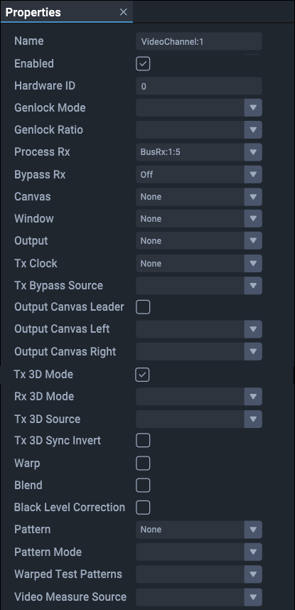
The Properties panel reveals all the features for any element in the Project. The Properties panel will always be showing the properties of the item or items highlighted as selected in the Project panel.
Note that illustrations in these user guides are examples of standard objects. The flexible nature of Compere allows for dynamic objects to be inserted into projects with their own dynamic properties.This allows for external devices and processes brought into a project to be controlled via Compere.
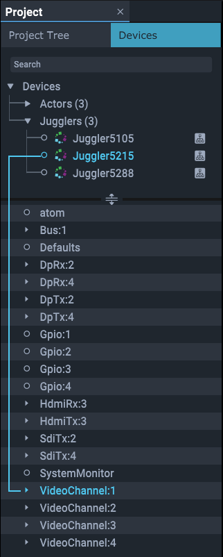
Members in the Project panel have their properties broken down by elements, for example a Juggler is broken down to each of its components and connections. Select a branch to see and edit the properties in the properties panel. For example, the properties of Video Channel:1.
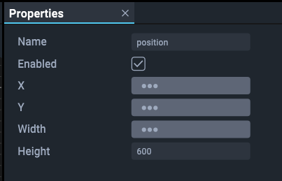
Note: multiple items, such as Jugglers or Canvas Outputs, can be selected in the Project panel, but only shared common properties and values will be shown. Unshared properties will be greyed out and unshared values will show ellipsis (...).
Example: multiple windows that only have a shared height value will only show that value, which can be edited for all:
Addressing properties remotely
Hover over a property label in the Properties panel to see its full address. This will appear as a tooltip but also in the bottom left of the status bar. Shift+Right-click to copy this path string for use in External Control commands.
Resources panel
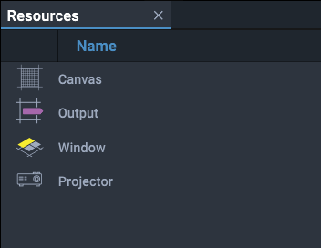
The Resources panel contains internal Compere objects that can be inserted into the project, including Canvas, Window, Juggler node components, programming nodes and default projectors.
Using Resources: Add, Select, Edit, Remove, Delete
•Resources can be dragged onto an assembly type panel (e.g. Timeline, Input feeds, VIsualise model etc.). This simultaneously adds them as branches of the Project panel.
•Resources and Devices shown in the Project panel, such as Jugglers and imported objects, can be dragged into an assembly panel.
•Objects are selected within an assembly panel to position, size or edit them, either by double-clicking them directly, or selecting them by name from the Project panel.
•When any object in an assembly panel is selected it will show a light blue border, and its name highlighted in blue in the Project panel. Its properties are now shown in the Properties panel.
•Right-click objects for contextual options: the selected object will be bordered in blue as well.
•To delete any asset, select it in the Project panel and press delete, or select it in the assembly panel and press Ctrl+Delete.
•To remove any asset from an assembly panel without deleting it from the project, select ‘Remove’ from its right-click context menu.
•Links between nodes and/or pins are deleted by selecting the receiving connector, and pressing delete.
Summary ❖Assembly panels are a visual representation to aid system assembly and configuration. ❖The Project panel holds all the members of the Project Tree with their individual configurations and links, whether displayed in other panels or not, and devices (Jugglers, Actors or other device sources). ❖Resources are added to a project by being dragged into an assembly panel. ❖Resources are taken out of a project by being deleted from the Project Tree. ❖When resources are removed from an assembly panel, they remain fully configured and interactive within the project. ❖Resources that have been removed can be dragged back from the Project Tree into an assembly panel, where their configuration, links, etc. will be correctly displayed. |
Canvas assembly panel (Jugglers)
The Juggler Canvas assembly panel represents the total pixels being processed by all Jugglers in the project group. In this overall space, Juggler Canvas Outputs (channels) are defined. Media inputs (Juggler Canvas Windows) are then placed anywhere in the overall canvas. The Canvas assembly panel appears in the default Layout for the Juggler View.
➢Display Configuration: Canvas Setup
Nodes assembly panel
This assembly panel creates all the throughput connections and processes within the Juggler system. Representations of each Juggler are shown here, with each video interface connector (bus and AV inputs and outputs), along with information on external connections and internal routing. Nodes is the assembly panel where you configure everything that comes into and goes out from each Juggler, and how these are connected and processed internally. NDI feeds are added and managed here. The Nodes assembly panel appears in the default Layout for the Juggler View.
The Nodes panel is also used for building Programming Nodes into dynamic functions.
➢Nodes: Connecting Juggler Systems
Page edited [d/m/y]: 18/07/2024
