Programming node types include sources, values, and logic processes. Flexible and powerful, they can be combined to create more complex interactions in Juggler systems, including automated events such as IntelligentSource™ failover.
Programming nodes can be added and manipulated by external controls, but are connected in the Nodes panel.
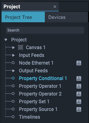
Drag nodes from the Resources panel into a Nodes panel and arrange or select them in the same way as Juggler nodes. Once added to a Project, they are listed in the Project panel, and when selected, their properties are shown for edit in the Properties panel.
Nodes that have been added into the Nodes panel are marked, just as Jugglers are, by an icon. Absence of this icon does not mean they are inactive, since a node removed from the Nodes panel remains in the project with all its properties.
•Nodes can be removed (Right-click menu) from the Nodes panel, but remain an interactive part of the Project, losing the ‘displayed’ icon in the Project panel. They can only be deleted from the Project panel.
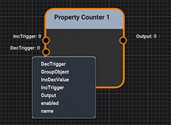
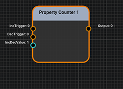
•Pins available to a processing node can be added to what is otherwise a minimalist representation, as required. Select the node, Shift+Right click for properties to add, and select the pin to add:
•Nodes have default names denoting their function but can be named for their purpose. The name appears in the title bar of the node.
•Those prefixed ‘Node’ initiate things, those prefixed ‘Property’ relate things via a process.
•Pins shown in orange take integer values, those taking strings are green, and blue indicated double values.
•Pins in a Nodes panel are linked by Shift+Left mouse dragging from source pin to target pin. In this way, values are communicated, transformed, used as triggers for other events, and so on.
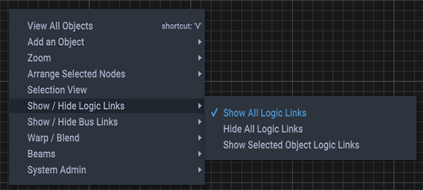
•Link lines can be hidden, shown or shown for only selected nodes. Right-click in the Nodes panel for the context menu:
•Links are deleted by hovering over the target pin and pressing Delete.
•Pin value colour: pins that exert control show yellow in the Properties panel, those that are being controlled show green.
•Additional dynamic properties can be added to nodes from the shortcut menu (Shift+Right click).
•Presets and Clones can be created from selected nodes.
Nodes that do things
Description An Ethernet receiver or transmitter. Used for external control messaging within a Compere system, over UDP or TCP. In client mode this is a message sender, in server mode it is a message receiver. Properties •Name: defaults to node type, rename for function as required •Connected: can be switched on or off by giving the value 1 = yes.0 = no •Host name: name or IP address of source to use •Input: as server, string message received •Output: as client, string to send by UDP/TCP •Port: default: 23 •Type: UDP, or TCP Client (send a string) or TCP Server (receive a string) •Input – remove end of line chars from input strings •Output – remove end of line chars from output strings •UDP read port: default 7781 |
Description Generates a waveform output. Constantly changing property values might include a position, colour or intensity, for example. The timing source is that of the server Juggler. Properties •Name: defaults to node type, rename for function as required •Amplitude (relative units) •Frequency (Hz) •Mode: sine or square •Phase: shift in degrees (180 is inverted) •Time: •Output: amplitude value |
Description Receives an input to append events to a named log file in a named location. Properties •Name: defaults to node type, rename for function as required •Directory: log file destination •Filename: log file name •Input: link to a node output being tracked for changes |
Nodes that relate and process values of other things
Description Connects to a configurable number of integer inputs. (The integer part of a double input will be read.) This node has two functions: A.To switch an output to be one of several inputs. OR B.To scan a series of inputs to give priority to the lowest-index positive (>0) input. Properties •Name: defaults to node type, rename for function as required •Number of Inputs: add number required •Output: Input pin number that meets the conditions. Switch mode •Switch Index: the number of the input to pass through (output becomes the value of this input). (Index: the index of Input_n is n. The index of Input_2 is lower than that of Input_3.) Priority mode •Priority Mode: when enabled, this scans instead for the lowest-index positive (>0) input. Example: Input_1 == 0, Input_2 == 50, Input_3 == 20. Output == 2 •+ Priority Latch: the pin number of the input to latch onto (stop scanning when matched). |
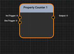
Description Receives triggers that match set values to increment or decrement the output by a step value. Properties •Name: defaults to node type, rename for function as required •Increment Trigger: set the value to compare with an input, and when it matches, increment the output •Decrement Trigger: set the value to compare with an input, and when it matches, decrement the output •Increment / Decrement Value: set the value by which to increment or decrement the current output when triggered. |
Description Configurable integer logic operator based on a flexible number of inputs with selectable mode to generate an integer output value. Properties •Name: defaults to node type, rename for function as required •Number of Inputs: add number required •Input: auto-labelled Input_# as generated •Mode: AND, OR, NOR, NOT, INVERT, ADD, SUBTRACT •Output: integer value to be output Mode output values
|
Description Apply values to a number of set destinations (paths) when triggered by a defined value. Properties •Name: defaults to node type, rename for function as required •Input Trigger: input value received. •Trigger Value: when the input matches this value, all outputs are triggered. •Number of Outputs: add number required. Generates a [Path] and [Output value] pair for each. •Path #: auto-labelled Path_# as generated. Enter the property paths required. Paired with: •Output #: auto-labelled Output_# as generated. Sends this value to the paired path when trigger value is met. |
Description Creates string outputs with values derived from paths. The path of any property in Compere can be copied using Shift+Right click on the property label in the Properties panel. Paths can be read in the left of the status bar when hovered over in the Properties panel. Properties •Name: defaults to node type, rename for function as required •Number of Outputs: add number required. Generates a Path and Output pair. •Path #: auto-labelled Path_# as generated, paired with: •Output #: auto-labelled Output_# as generated; adopts the value from the paired path. |
Page edited [d/m/y]: 23/06/2023
