This section describes the Juggler Canvas: the arrangement of video pixels on outputs assembled into a display directly from Juggler connectors. In comparison, when Actor outputs are assembled in the Input and Output Feed panels, this selects source pixels and places them on the arrangement of Actor device outputs.
In addition, Compere can achieve virtual canvases operating picture-in-picture regions over the display (this is covered in the Actor user guide).
A Canvas in a Juggler system comprises all available pixels in a Juggler system as a whole. Within this, Outputs to the resolution of available devices are positioned. Depending on the firmware type for your Juggler, direct one-to-one feeds can be made to these Outputs, or to Windows as areas anywhere in the Canvas, even across output boundaries. Which type of Juggler you have – Warp/Blend or Windowing – is defined in its factory build (you can see which, in Juggler > Properties, under Internal Processor, Capabilities).
The following description is for Windowing Jugglers.
See also:
➢Display Setup via MPCDI – canvas and outputs are pre-configured, defined and uploaded along with warp, blend and black level files
➢Output Canvas Bus – a configuration for maximising numbers of inputs directed to windows moved anywhere on very large canvases
Canvas, Canvas Outputs and Canvas Windows
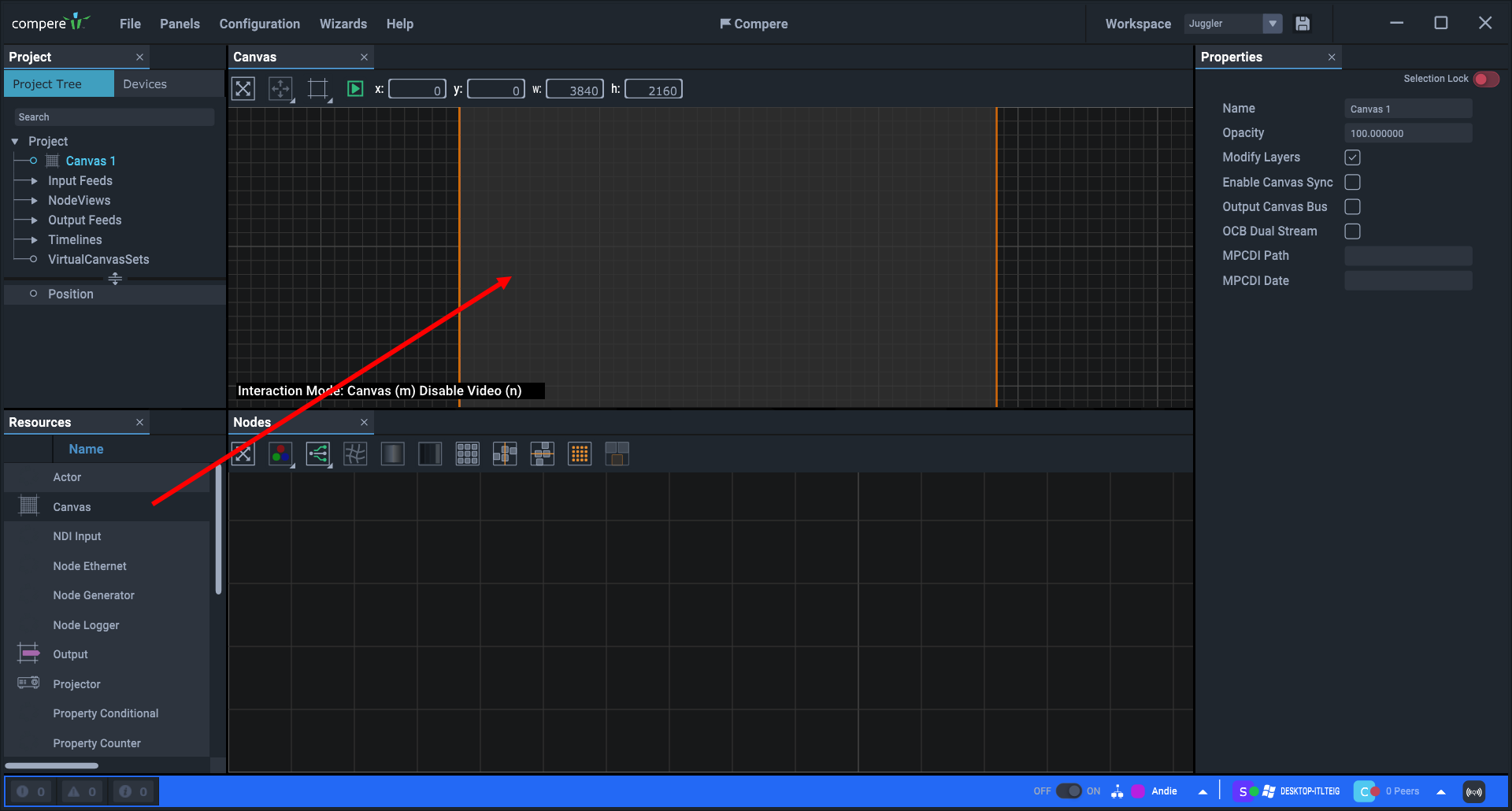
The Canvas, the Outputs on it, and Windows in them are all laid out in the Canvas assembly panel, simply dragged there from the Resources panel. Each of these will be connected by Compere into the Juggler system, using the Nodes assembly panel. As each element is dragged in, it is added to the Projects panel, its properties become available, including how the element is named.
•Drag a canvas from the Resources panel into the Canvas assembly panel. This will be added at default coordinates (0,0) but can be moved.
•You will now have the grey overall canvas maximised to full view in the panel. Since it is selected, it will have an orange bounding box. The initial default dimensions are 3840 × 2160 (4K).
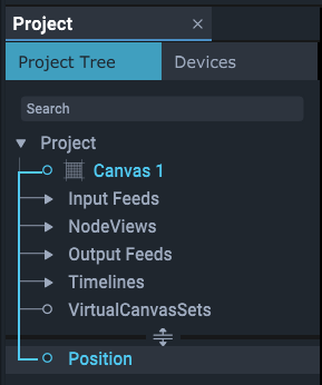
•The Project panel will now contain a branch for this canvas, and the Properties panel is populated for the canvas.
•You may only need one canvas.
Below the canvas, the Interaction Mode is shown:

This mode switches the selection layer between the Canvas, Outputs, and Windows.
Pressing ‘m’ switches between the three types of canvas objects so they can be selected and moved independently. Once set up you will not need to move the canvas, but you will add and position Canvas Outputs and Canvas Windows within it.
In ‘None’ mode, canvases can be dragged within the grid to position them using Shift+left mouse, but not to resize by dragging.
Mode selection is also available on the toolbar button or on the right-click menu as ‘Interaction Mode’.
Disable Video: press ‘n’ to toggle between the outlines of Outputs and Windows and any connected video input.
Menus, moving, sizing
Right-click context menus are available everywhere in the Canvas assembly panel. Many of these options also have keyboard shortcuts and mouse operations as in other panels.
➢See Keyboard Shortcuts
Canvas Panel Toolbar

•The first button operates the same as pressing the ‘v’ key and will bring into scope everything in the panel.
•The second button refers only to Canvas Windows, and provides a list of common positions (top, bottom, left, right, centre and fullscreen).
•The third ‘frame’ icon operates the same as pressing the ‘m’ key, switching between object types for selection.
•The green / grey arrow button icon operates the same as pressing the ‘n’ key, to enable or disable NDI preview in the Canvas panel.
With the canvas selected in the Project panel, configure its properties in the Properties panel.
Canvas Properties
Name
Name this canvas clearly. Multiple Canvases are by default numbered sequentially. It will be listed in your project and selectable for connection to Jugglers. Names can also be changed in the Project panel by double-clicking the name there. Use unique names.
Opacity
Set the opacity of all Windows on this Canvas. This will not be applied to any bypassed video channels.
Modify Layers
Uncheck to fix the layering of Canvas Windows. Check so that selecting any window brings it to the top.
Enable Canvas Sync
For cross-Juggler synchronisation of Juggler Canvas elements. (Not yet implemented.)
Output Canvas Bus
On OCB firmware-enabled systems: switch bus mode to place the canvas onto the bus. See Output Canvas Bus.
OCB Dual Stream
Split inputs in 4-lane output canvas bus systems.
MPCDI Path
On warp and blend firmware systems: if using MPCDI data, enter the relative folder path where you choose to keep MPCDI data files.
MPCDI Date
Date of the MPCDI source being used.
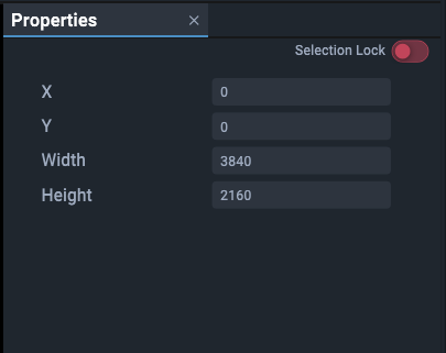
Canvas > Position
X and Y, Width and Height
Specify the dimensions of a Canvas.* If using more than one Canvas, these are all inserted at 0,0 X,Y coordinates, so set the X and Y offsets to displace a second Canvas.
* The resolution (Width and Height in properties) of the Canvas for a Project is set to at least the maximum overall requirement. It does not necessarily represent contiguous physical space, only the number of pixels available to be claimed by outputs (see Output Setup).


