When Jugglers are added into the network and assigned to project groups, they are recognised and added into the Project running for that project group, becoming visible in the Project panel.
•Drag a Juggler or Jugglers from the Project panel into a Nodes assembly panel. If necessary expand the Nodes assembly panel and press V to view all, or zoom in to reveal more detail and text. Drag further Jugglers in, and position them on the grid as best fits your purpose.
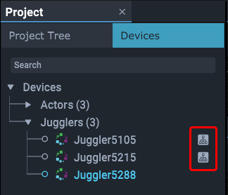
•These Jugglers are now nodes. A Juggler that has been added to the Nodes panel has an indicator against it in the Project panel:
Naming and arrangement
With many Jugglers in various roles, you are probably working to a diagram of how they are connected and their functions. It is useful to name and arrange your Jugglers in the Nodes panel (and/or use the alignment tools – see below) to best represent your diagram.
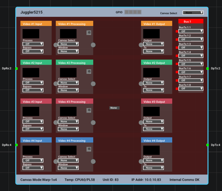
Juggler title bar
Identifies the Juggler name and allows the Canvas to be selected for all video channels in the Juggler.
GPIO
These four indicators correspond to the GPIO HD-BNC ports on the back panel 1-4 left to right.
Grey: not enabled (in Juggler properties)
Red: enabled but no signal present
Green: enabled and connected
Juggler node status bar information
Canvas Mode
Reflects the type of Juggler firmware being used: Windowing, or Warp and Blend (MPCDI).
Temperature
For internal monitoring of the Juggler.
Unit ID
Last 2 digits of the Juggler module’s IP address, to provide an identifier within the project group.
IP Address
Full IP address of the Juggler module.
Internal Comms
Indicates the status of communication within the Juggler module between the Linux processor running Compere and the main board processing the pixels.
The four Juggler video channels
Every Juggler has four channels of processing: 4 × Rx, 4 × Tx. Available processing channels are arranged left to right and coloured; unavailable channels (e.g. being utilised for the bus) are grey. Here are the essential parts of channel 2:

On the left is the square green Juggler module input pin, here DisplayPort #2 (DpRx : 2). It is showing green because a valid media feed has been detected on it.
Hint: Click any input or output pin to show its properties in the Properties panel.
➢See Video Channels Properties
Video Input
•This block accepts either the input to this video channel, and/or an input from the bus.
•With NDI enabled, the input video for the channel will appear here.
•It can connect an input directly to a matched output, bypassing any further processing, or it can process an input in order to position it on the output canvas (i.e. in a named canvas window).
•An adjacent input pin does not have to be handled by this video channel. It could instead be selected in the bus for this Juggler, in order to pass it on to a different Juggler to handle (process to a window, or bypass to a matched output).
Process: this selector chooses the source for this channel to process. Select ‘Off’ if nothing to process. In the example shown here, DpRx : 2 has been selected as an input to process. This has connected it automatically to the Video Processing block, adding the green connecting link. You might equally want to take a media stream from the bus as an input for this channel to process.
Bypass: media can, if required, bypass all processing and go straight to the same-numbered channel output. Select ‘Off’ if nothing to bypass. This direct routing reduces bandwidth if no processing is required. A warning is given if the resolutions do not match and the pin will be yellow.
You can bypass one input and simultaneously process another in the same video channel.
Video Processing
If you process an input, you are locating it in a window on a canvas.
Canvas Select: select a named Canvas within which this channel will be displayed. The list is populated from Canvases added to the Project, named and placed in the Canvas assembly panel. This can be set from the title bar to apply to all available video channels per Juggler.
Window: select a Window of the selected Canvas, in which the channel media will be displayed (if required). The list is populated when the Canvas Windows are added and named.
Video Output
Output: select a Canvas Output for this channel. The list is populated when the Canvas Outputs are added and named.
Tx: select the port out from Juggler module to a display (square pin on the right-hand side of the Juggler node in Compere).
 |
See also:
➢Media connectors: Connecting Inputs and Outputs
Colours, pins and links
Channel headers, pins and links are grey if unavailable (for example channels dedicated in a Juggler module to a bus). Available channel headers will be coloured when available. Pins and links will be red if disconnected, and green if connected. A yellow pin indicates an incompatibility.
The small square pins on the left and right edges of a Juggler in Compere, are labelled as channel inputs (Rx, left) and outputs (Tx, right).
The larger round pins inside a Juggler in Compere represent connection points for processing media through a channel, and their colour, together with the status bar indicator. the background colour of the Juggler node and of its name in the project tree, is diagnostic:
Summary:
•The status bar internal comms indicator for a Juggler in the node view is green – ‘OK’ when Compere and the Juggler are communication correctly.
•The status bar internal comms indicator for a Juggler in the node view is red – ‘Internal Comms Fault’ when Compere and the Juggler are not communicating. Reboot the Juggler to correct this.
•The status bar internal comms indicator for a Juggler in the node view displays the last known indicator state if Compere is not running on the Juggler.
•The Juggler name in the project tree is dark grey if Compere on the Juggler is not connected to Juggler SW
•The background colour of a Juggler in the node view is red if the Juggler is not present in the current failover peer list
•The background colour of a Juggler in the node view is grey when the Juggler is present in the current failover peer list
•The Juggler name in the project tree is dark grey if the Juggler is not present in the current failover peer list
•The Juggler name in the project tree is light grey if the Juggler is present in the current failover peer list and Compere on the Juggler is connected to Juggler SW
|
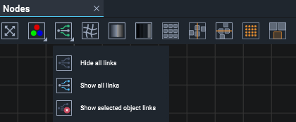
Links are drawn between pins to show these connections, and naturally can become difficult to trace and distinguish with many units. The Nodes toolbar button allows some clarification:

‘Show selected object links’, for example, will show links to, from and inside a selected Juggler only.
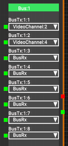
The square pins in the Bus block (upper right of each Juggler node) are the bus connections. These pins will show green when valid media is available on the bus lane.
Multiple selection
Whilst properties cannot be displayed for more than one object, you may want to move or arrange multiple Jugglers. Select a node by double-clicking on it, or click on its name in the Project panel. To select several nodes at once use Ctrl+select.
Nodes panel toolbar

|
Bring all objects into view (shortcut key: ‘V’). |
|
Select colour beams on or off for all outputs, all Jugglers in the Project. The context menu (right-click on a Juggler in Nodes) also offers beam controls for the outputs of the specific Juggler. |
|
Display links between nodes selectively. |
|
Enable/disable warp. |
|
Enable/disable blends. |
|
Enable/disable black-level offset. |
|
Arrange selected nodes (e.g. Jugglers) in a grid pattern. |
|
Arrange selected nodes in a single column. |
|
Arrange selected nodes in a single row. |
|
Mini Map: Show a miniature map of all nodes and the position of the current view. |
|
Selection View: Make the position of a selected node the viewpoint for any node then selected in the Project panel. |
The Juggler bus options
On the side of the Juggler node is the bus block. Jugglers can have one of two optical fibre bus options: 4-lane (2 × Rx and 2 × Tx video channels) and 8-lane (4 × Rx and 4 × Tx video channels). The pins on the left show green when the bus pin is connected. This example shows a fully connected 8-lane Juggler. Its green title bar shows it is active. An inactive bus is red.
Wider bus options with 12 and 16 lanes are being developed.
For how the bus connections correspond to the physical cabling, see Bus Connections in a Juggler System.


