In a windowing Juggler system, you will have set up your display Canvas, with a number of Canvas Outputs and Canvas Windows. The Outputs can be named or numbered to identify the area of Canvas on which you may want to display media. Any number of Windows can be positioned and scaled dynamically anywhere on the Canvas, across the boundaries of the Canvas Outputs, to which media streams can be assigned.
Throughput for a single Juggler
In the top bar of the Juggler, select the Canvas name that this Juggler will address. This list is populated when Canvases are created and named. Selecting here will populate ‘Canvas Select’ in all available video channels for the Juggler.
Juggler input pins, on the left edge of the Juggler, are named by type, e.g. DpRx : 2, meaning a DisplayPort input on channel 2 of the Juggler. If no valid media are present on that physical port, it will be red. If valid media is present, it will be green.
From the list of available feeds in the Video #2 Input ‘Process’ selector, add an input. The Process block will now be linked to the Video #2 Processing block. If valid media is present, pins and links will be green. If you have ‘Enable NDI Confidence Monitors’ selected in the Properties of each Juggler, this will help verify that a media stream is connecting correctly. NDI monitors can be seen in the video channel input and output blocks of a Juggler in Compere, and in the Canvas assembly panel. This illustration confirms that video is being received from the named input and video is being presented to the listed Tx pin – in this case the canvas as a whole has a test pattern.

In the Processing block, you decide where this is to go next. There are other processes you can add, but for now, just ensure you have the canvas you want to use.
In the Video #2 Output block for this channel, ensure the Tx has the appropriate destination port selected. Using the Output selector, choose which Canvas Output area is required. The list is populated as Canvases are added to the Canvas assembly panel. This will remove the direct link to the Output block because in order to display the media we need to say where on the overall Canvas it is to appear, i.e. in a Canvas Window. You can use a Juggler test pattern as a background of the output when media is not present:

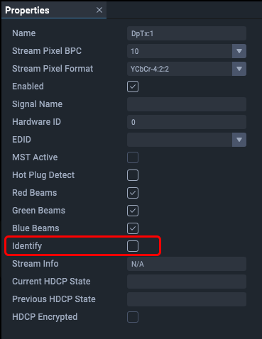
Reminder: You can identify a Juggler output in the real world by checking the Identify box in the Juggler output properties:
This checkbox is ‘push-to-show’, and will temporarily cause the output device to flash red and then green.
Now assign the video channel to a Canvas Window in the Video Processing block. The selector list is populated by the addition of Windows in the Canvas assembly panel. Canvas windows can be positioned anywhere in the Canvas, so what you see on the output display will require this Window to be positioned somewhere over the selected Canvas Output for this video channel, as here:

Now we have NDI showing an input signal is being received, that it is being presented to a named window, and where it is being displayed on the named output.
