There are two modes of use for the Juggler bus: the ‘Input Bus’ and the ‘Output Canvas Bus’. The mode of your system will be established in its firmware. This section relates mainly to the former, and describes the bus in general.
The physical Juggler bus can be configured in two ways: as a 4-lane ‘half’ bus via SFP modules, or a an 8-lane ‘full’ bus with MPO connectors (see: Connect a Juggler Data Bus). In Compere this makes no difference to configuration, and the bus is automatically detected.
A further option is a high-bandwidth configuration of the 8-lane bus, in which lanes 4 and 8 share their capacity with the other six.
Juggler bus bandwidth is UHD (3840 × 2160) at 60fps 10bpc 444 capable (or equivalent bandwidth) per bus lane. The high-bandwidth option (6-lane) is capable of 4K.
A juggler System is a group of 2 or more Jugglers on a data bus. In Compere, any input can be sent onto the bus and redirected to another Juggler module to be picked up there as an input, to process and direct onto a display. This configuration is stored in the Project file.
The Bus connection block is represented inside the Juggler in the Nodes panel of Compere.
➢See also: Physical bus connectors, Connecting a System in Compere
8-Lane Bus
24 or 30 bpp – (30 bpp limited to UHD at 60 fps or equivalent)
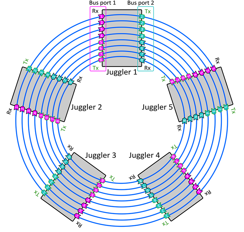
There will typically be only one bus in a Juggler, but two are possible (see Bridging Two 8-Lane Buses). The number of pins in the bus are those available lanes on the installed bus. Any Juggler can then place up to four video channels on the bus, and receive up to four as inputs. See in the diagram below how Jugglers interconnect, and the bidirectional flow of the bus itself, indicated by the pointers of the green pins.
Any Juggler can therefore place media onto the bus, from where any other(s) can stream it off as an input.
In Compere Nodes panel
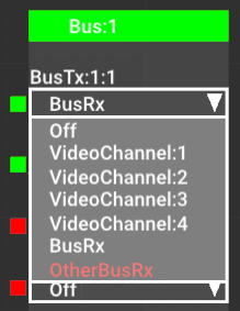
•The red/green markers on the left of the Bus nodes indicate where a bus input (Rx) exists (green).
•The drop-down list indicates what this bus node is to send out (Tx). This could be nothing (Off), an unprocessed video channel input, or whatever is being received on the bus from the previous Juggler in line (an Rx in the list).
The drop-down selector in the Compere Juggler Bus offers these options:
BusRx
Selecting ‘BusRx’ here will simply pass on this Juggler’s received bus, so Juggler 1 BusRx:1:1 will connect internally to Juggler 1 BusTx:1:1 and be passed on to Juggler 2 BusRx:1:1 and so on, as in the diagram above.
Video Channels
The 4 video channels listed are the media channels of this Juggler. By selecting an available channel that has an input (green), this input will be sent out onto the bus and can be streamed off as an input anywhere else along the bus.
OtherBusRx
A single Juggler can have two 8-lane bus interfaces. One example of use would be to link two racks of Jugglers in an input failover (IntelligentSource) configuration. See Bridging Two 8-Lane Buses.
Example: For Juggler 1 in the rack, select an input source for its Video #2 Input. Now, in the Bus block, select Video Channel 2 for BusTx:1:1. On Juggler 2 (next on the rack bus), the pin for BusTx:1:1 will change to green to show a valid media source is now present on that pin. This media is now available on this lane of the data bus, from where the channel can be selected as an input by another Juggler to process. Example continued: On Juggler 2, select BusTx:1:1 as the input to Video #4 Input. Media from Juggler 1 channel #2, will now pass to Juggler 2 channel #4, from where it can go to a Canvas, an Output, and a Window. If NDI is enabled, the media will show present on this video channel in the Nodes panel. |
Connect the bus as required for your data. You do not need to make unnecessary connections.
4-Lane Bus
This option has half the capacity of the 8-Lane bus, operating through Juggler SFP modules. The arrangement is similar to the 8-Lane diagram, but can be imagined as pins 1 to 4 only.
High Bandwidth Bus
To increase bandwidth, lanes 4 and 8 can share their capacity with lanes 1-3 and 5-7. Effectively this becomes a 6-Lane bus, with lanes 4 and 8 unavailable to separate video channels. This is enabled in the main bus properties (see below).
Page edited [d/m/y]: 20/01/2023

