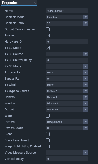
Up to four video channels are available per Juggler. Select each video channel branch for its properties.

Name
The default name of video channels is VideoChannel:# (1-4)
Genlock Mode
Free run or lock to a source (see: GPIO Genlock Example in the ‘Operating Juggler 1’ user guide).
Genlock Ratio
This is ratio of input to output frame rate:
1:1 For normal operation (e.g. 60 fps in to 60 fps out)
1:2 (e.g. 60 fps in to 120 fps out) for passive to active stereo
0 = 1:1, 1 = 1:2, 2 = 2:1
Output Canvas Leader
Applies to Output Canvas Bus mode only. Check for this Juggler to adopt the lead for this channel (i.e. send this video channel to a display device).
Output Canvas Left (if Leader for this channel)
Applies to Output Canvas Bus mode only. Select the Tx pin on this Juggler to carry the left-side part of the output pair.
Output Canvas Right (if Leader for this channel)
Applies to Output Canvas Bus mode only. Select the Tx pin on this Juggler to carry the right-side part of the output pair.
Hardware ID
Information only. The internal recognition identifier in the respective Juggler. Be sure to understand the correlation with the physical interface panel identification.
Connectors in Compere project are identified by type and number, as follows:
DisplayPort: base 000 (so numbered 001, 002, 003, 004)
SDI: base 100 (so numbered 101, 102, 103, 104)
HDMI: base 200 (so numbered 201, 202, 203, 204)
BUS: base 300 (so numbered 301, 302, 303, 304
Tx 3D Mode
Select to enable 3D out.
Tx 3D Source
Select the required video source.
Tx 3D Shutter Delay
Select angle in degrees (0 to 359).
Rx 3D Mode
Select from: Mono, Left Eye only, Left Eye (Right=Other), Right Eye (Left=Other), or Right Eye, with Left Eye from Channel 2, 3 or 4)
Process Rx
Select a Bus channel to receive media in or place media out, or none.
Bypass Rx
Select to direct a signal from the Bus to the corresponding channel Tx (must be matched resolution).
Tx Clock
Sync this output port to an available option.
Tx Bypass Source
Select the input to send through bypass.
Canvas
Name of the canvas containing the output that this channel feeds.
Window
Name of a window on this canvas to which media is sent via this video channel.
Output
Name of the output on this canvas to which the TX port connects.
Warp (Warp & Blend configurations only)
Enable/disable warp.
Test Pattern
Select a test pattern to display (None; 4 quadrant colour Y ramp; Black; Chequerboard; Colour Chequerboard; Flat; Grid; X ramp; Y ramp.
Test Pattern Mode
Select On, Off, or Mix to overlay the pattern on media.
Warped Test Patterns (Warp & Blend configurations only)
Apply warps to test patterns.
Blend (Warp & Blend configurations only)
Enable/disable blends
Black Level Correction (Warp & Blend configurations only)
Enable/disable black level correction
Warped Highlight Enabled (Warp & Blend configurations only)
Display green fill where video is warped away from rectangular bounds.
Video Measure Source
Select the video source for which you want to see details, listed under the Juggler in the Project panel. See Video Measure.
Vertical Delay
Adds a fractional amount of vertical delay to an output, specifically with the aim to minimize throughput delay to the bare minimum.
Page edited [d/m/y]: 20/01/2023