Example: Use an input VSync
In the Juggler system, the first in line is designated as providing the source for genlock.
In Compere
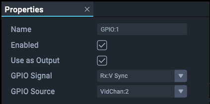
This first Juggler’s GPIO:1 is set to be an output, using a video channel media input as its source, and the signal it is sending as the V Sync is is receiving from this source (expressed as Rx:V Sync) (see terms above).

➢See Compere 1.0-5 User Guide: GPIO Properties.
The next Juggler in line has its GPIO:2 set to be in input, in other words, simply receiving from the attached cable.
Its GPIO:1 is set to be an output, using its GPIO:2 as its source (the signal need not be specified).
This is repeated down the line, the last of course not needing to be assigned a sending GPIO.
Connections
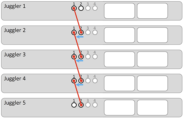
Five Jugglers would therefore be cabled as follows:

Genlock Mode
Now that every unit has a genlock signal, each that has a signal received on its GPIO:2 can use that for the output genlock mode in Compere.
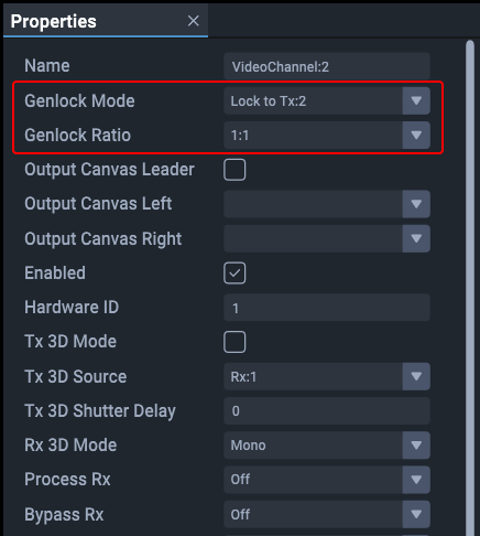
The first Juggler has no signal on GPIO:2, so uses the same signal received on Video Channel 2 (Compere, JugglerName > Video Channel 2 > Properties):
