So far we have looked at using the bus as a transport system for taking an input from one Juggler and sending it to another to handle the display output. The canvas is effectively assembled at the end of the process. This has its limits as display sizes increase and the number of inserted windows multiplies.
Whilst every Juggler has four video channels, and up to four input ports and four output ports, there isn’t always a match between the number of inputs required and number of outputs. For example, you may well want many input options to many simultaneous canvas windows, on a very large overall canvas, comprising a much smaller number of display devices. This will require many input signals to be processed and sent to many windows, each of which can be anywhere on the overall canvas, on any canvas output, at any time, whereas the physical displays need the output connectors of only a few of the Jugglers.
The OCB Difference
This is done by operating the Juggler bus system in a different way. On an Input bus, Jugglers are described as selectively processing ‘Input > Process > (Bus) > Output’ – across each Juggler video channel. (left to right through the Juggler in the Nodes panel). In other words, inputs can be selectively and individually placed on and taken from the bus before deciding their display destination. It also means there can only be a maximum four Windows on a Canvas.
In an output canvas bus (OCB) setup, the four Juggler ‘Video # Processes’ (including their canvas location) are diverted automatically onto four bus video channels, which carry the whole canvas assembly (Canvas, with any number of Outputs and Windows) around. In an 8-lane bus, two bus lanes are assigned to each of these bus video channels*, which then feed two output connectors each. One Juggler is assigned to each bus video channel to send these outputs to its Tx ports to display.
* On a 4-lane bus, these can do the same by enabling ‘dual-stream’ channels.
In this mode, any number of windows (media input) can be moved anywhere on the canvas (overall display) regardless of which Juggler hosts the input media, and which is driving the actual display output.
It is essential to have an understanding of how an output canvas bus works, but to make it easier to set up, there is the OCB Wizard. |
Video Channel Leaders
•Allocated Jugglers take one bus video channel (only) onto two of their Tx ports.
•A juggler that takes a bus video channel output and places it on its Tx ports ‘takes the lead’ for that video channel. In that sense, a Juggler that provides the output connection for video channel 1 is a ‘leader’, one that provides the output for video channel 2 is also a ‘leader’, and so on.
•Any Juggler that provides no physical output is referred to as a ‘follower’. In reality it just has no channel lead role.
•Every ‘Video # Output’ in the system uses the same canvas output as named by the leader of that channel.
Example: Juggler A has its VideoChannel:1 property set to ‘Output Canvas Leader’ and its Video #1 Output is set to an Output named ‘Top Left’. Juggler B, C, D ... will all set their Video #1 Output also to Output ‘Top Left’.
Populating the Canvas (Canvas Panel)
A canvas comprises up to four video channels, carried over the 8 bus lanes of a ‘full bus’ system (or 4 dual streams of a 4-lane system). Each bus video channel is mapped onto two lanes, providing left and right parts for that canvas output to be delivered by a Juggler taking the lead for that bus video channel.
These paired elements of the overall display can be arranged as required. Here are three common linear arrangements, but the pairs don‘t have to be aligned to each other. Names for the canvas outputs are just suggestions that will help in constructing the flows.
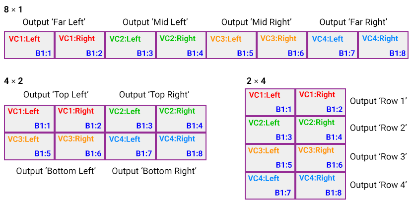
When a canvas output is now added onto the canvas in the Compere Canvas panel, and then linked to one of these dual video channels in a Juggler node, it will represent the two bus lanes – i.e. as wide as two outputs. The left half of this will go to one Tx port of the lead for the video channel, the right half to another Tx port.
Example: the 4 × 2 arrangement above:
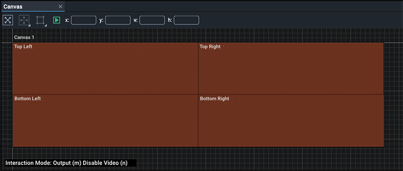
A similar output canvas mode is available to 4-lane bus systems, but instead of each video channel connecting to two bus lanes, they each connect to one. In effect this is as above, but with only a single output. By applying a further ‘dual stream’ mode, this also can be split into two outputs.
Output Canvas Bus Workflow (manual method)
To set up an OCB system in this way, requires a different workflow from the Input bus. A schematic diagram is important to work from, with systematic naming of Jugglers, canvas elements and output devices. In this way, between diagram, physical racking and Compere, you will more easily see the sequential arrangement of all the components.
Add the Jugglers to the Nodes panel
•Drag all required Jugglers in the network from the Project panel into the Nodes panel.
•Name the Jugglers for their roles, e.g. Juggler3456 Ldr1 (this Juggler is leader for video channel 1), Juggler3457 F (this Juggler is a follower only).
•Arrange the Jugglers logically. For example, you may want to lay out the leader Jugglers at the top or group them separately.
Connect all inputs
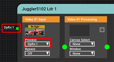
•Connect each input pin on every Juggler to its corresponding video channel. Example: DpRx1 to Video #1 Input, Process = DpRx1:
Establish the Canvas
•In Compere, drag a Canvas from Resources into the Canvas panel.
•Size the Canvas in its ‘Canvas Bounds’ properties for the overall pixel resolution of the whole display area.
•In the Canvas main properties, check ‘Output Canvas Bus’. This identifies all its child Outputs and Windows as coming from the bus.
•For 4-lane bus configurations with the same left/right output pairing, select ‘OCB Dual Stream’. Otherwise all the bus video channel will go to a single rather than paired output.
•From Resources, add the required number of Outputs onto the Canvas to fill/fit the Canvas, bearing in mind that each bus video channel will provide 2 Tx feeds, ‘Left’ and ‘Right’ (i.e. double width).
Do not manually size these outputs, but it can help to name them for their positions (e.g. ‘Output top left’ rather than default ‘Output 1’ – see the illustration, above).
•Paired outputs? An odd number of display devices means that one half of one of the outputs will be used. This unused part will simply lie off the canvas.
Set each bus mode to ‘Output Canvas’
•For all these Jugglers, and every bus on each (you can multi-select them all in the Project panel) set the bus properties to ‘Output Canvas Bus’. This will change the way the whole bus is connected and operates.
•The bus drop-down menus will now be auto-populated with their set channels. Example: for an 8-lane bus system:
BusTx:1:1 and BusTx:1:2 carry Video Channel 1 Output
BusTx:1:3 and BusTx:1:4 carry Video Channel 2 Output
BusTx:1:5 and BusTx:1:6 carry Video Channel 3 Output
BusTx:1:7 and BusTx:1:8 carry Video Channel 4 Output
Do not change any of these auto settings.
Which Jugglers will be providing the physical output connections?
One Juggler must be assigned to lead each bus video channel. Example: select VideoChannel:1 from Juggler leader1 in the project panel. In its properties, check ‘Output Canvas Leader’.
•Refer to your schematic drawing for which Leader Juggler is feeding each display (e.g. from left to right)
•On the Leader Jugglers, assign one video channel that will be connected to an output device, to ‘Output Canvas Leader’ in the properties.
Example:
Juggler Ldr1 claims Video Channel 1 as Leader, taking Bus lanes 1 & 2 (other channels available as Follower)
Juggler Ldr2 claims Video Channel 2 as Leader, taking Bus lanes 3 & 4 (other channels available as Follower)
Juggler Ldr3 claims Video Channel 3 as Leader, taking Bus lanes 5 & 6 (other channels available as Follower)
Juggler Ldr4 claims Video Channel 4 as Leader, taking Bus lanes 7 & 8 (other channels available as Follower)
•Set up/check the EDID of all these Juggler leader output connectors. These may be custom-supplied to suit the particular configuration.
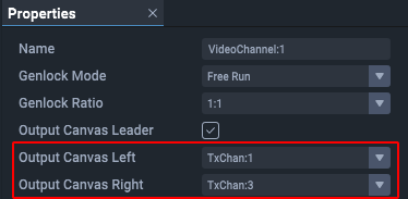
•In the properties for each of these channel leads, assign ‘Output Canvas Left’ and ‘Output Canvas Right’ in their drop-downs, to the output connectors for that Juggler (e.g. TxChan:1 and TxChan:3):
Route the lead Juggler outputs to the canvas outputs
•Find Juggler video channel 1 leader in Nodes, and in Video #1 Processing assign the Canvas, and select the required canvas output name in Video #1 Output. (Ignore the Tx box.)
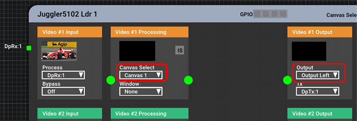
•The canvas output in the Canvas panel will now have assumed its dual (left/right) dimensions, so now locate it correctly in the canvas.
•Do the same for the Juggler leading video channel 2, and assign Video #2 Processing to the Canvas and Video #2 Output to its required output name.
•The canvas output will now have assumed its dual (left/right) dimensions, so now located this correctly in the canvas.
•Repeat through all leader Jugglers until all video channels are covered.
Route all other Juggler non-lead outputs
•In all Jugglers, each remaining video channel needs to be assigned to the canvas. Do this irrespective of any active input on that Juggler‘s video channels.
•In every Juggler where the Juggler is not managing (leading) that channel, set ‘Video # Output’ in the output drop-down to the same output name that the leader for that channel number is managing. Example: channel lead 1 is addressing ‘Output Top Left’, so in the ‘Video #1 Output’ block for all other Jugglers, also select ‘Output Top Left’ from the Output drop-down.
Add the media windows to the canvas
•Add Windows to the canvas as required. Name, size and position these as in any Compere system. These reflect the all the inputs you wish to display. They may have preset positions or groups, but each can now be moved seamlessly anywhere on the entire canvas.
•Assign these named windows as required to Juggler inputs (under Video # Processing):

•Windows can be moved on or off the Canvas; when off, their content will not appear on the display. (See also: Create and Recall Canvas Arrangements.)
Since the whole canvas is on the bus, all window information is carried around with it, so unlike the Input bus mode, the media is not going to the same Juggler‘s output (on the right in the node), but straight onto the bus.
Page edited [d/m/y]: 26/09/2022