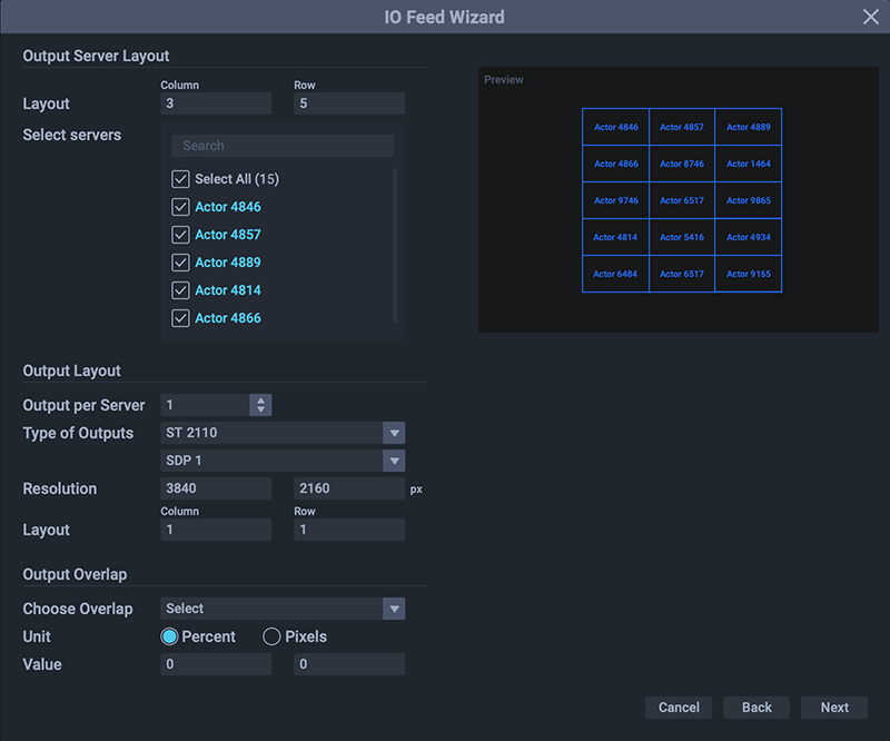
For regular flat rectangular displays, the I/O Feed Wizard (top menu > Wizards) will very quickly arrange rows and columns of viewports over rows and columns of Actor device outputs. This saves calculating the distribution and setting sizes individually, and taking account of bezel compensation or projector overlap.
Input Configuration
This page will establish a single viewport or an array of contiguous viewports to select pixels from an input.
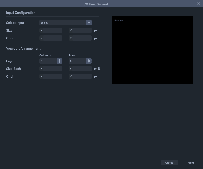
Select Input
All inputs in the Project are available; select the one for which you want to apply viewport(s).
Size
This will normally be the resolution of the selected input.
Origin
An input origin represents where in the Input Feeds panel it will be placed. The first would normally be at 0,0. Inputs can be moved by measure or by dragging if required, once the wizard has been completed, and will take their viewports with them.
Viewport Arrangement
This will create an array of viewports, from 1 to the number required, laid out and numbered in rows and columns.
Layout
Select the number of rows and columns.
Size Each
Click the padlock icon to auto-size all viewports to fit and fill the input resolution. Alternatively, enter the default size to apply to all viewports.
Origin
The origin of the array is relative to the position of the input. Unless you want the array of viewports not to us the same origin as the input, leave this at 0,0.
The wizard will now show a preview of the input arrangement:
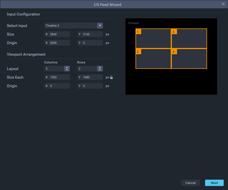
The ‘Next’ button will turn blue; press to continue to output configuration.
Output Configuration
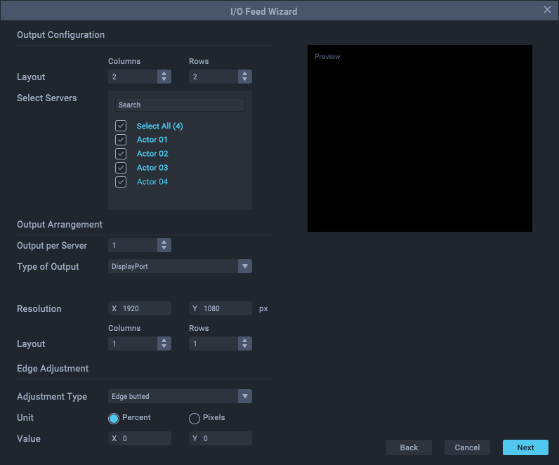
This page will gather the required device outputs to assemble them in rows and columns and then distribute the viewport outputs over them. The wizard assumes that all devices have 1, or the same number of, outputs (GPUs).
Arrangement
Select the number of rows and columns into which the servers (Actor, Conjuror, Delta) will be arranged.
Select Servers
From the list of all servers detected in the Project, select those with the required GPU outputs.
Outputs per server
Enter the number of GPUs in each server (usually 1 but this must be the same for all).
Type of Output
Select the graphics output format. If ST 2110, then select the applicable SDP file below
Resolution
Select the common resolution for all outputs.
Output Arrangement
Select the rows and columns to arrange the output positions per server.
Edge Adjustment
Adjustment Type
Select edge-butted (LED tiles), underlap (bezel compensation) or overlap (for projector blending).
Unit
Select percent or pixels.
Value
Add the percent or pixels required .
The wizard will now show a preview of the output arrangement.
Press ‘Next' to preview the list of servers and assigned viewports layout before pressing ‘Create’ to finish.
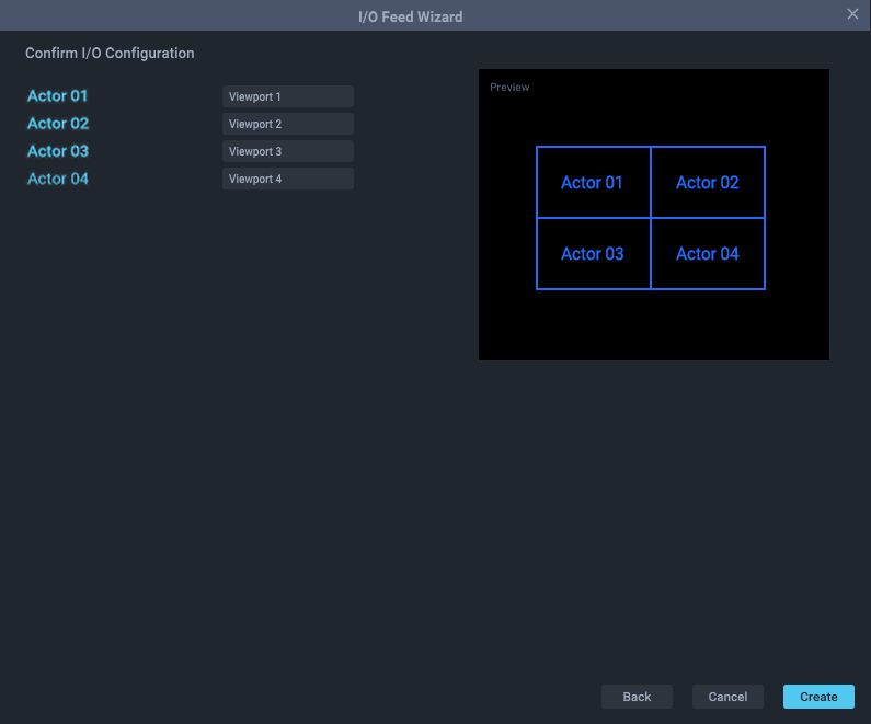
The input, viewports and output arrangements are now complete:

Adjustments
Once a matrix array of inputs, viewports and outputs, has been constructed, every element in it can be manipulated in exactly the same way as described for manual configuration in the Input Feeds panel and the Output Feeds panel. This includes the addition of other input sources and other device outputs.
There is no ‘restore’ function, but Compere can save your arrangements as Presets or Clones (see the Compere UI User Guide). Clearly this wizard is more useful for larger arrays and setting up, as in this example of an ST 2110 15-panel display:
