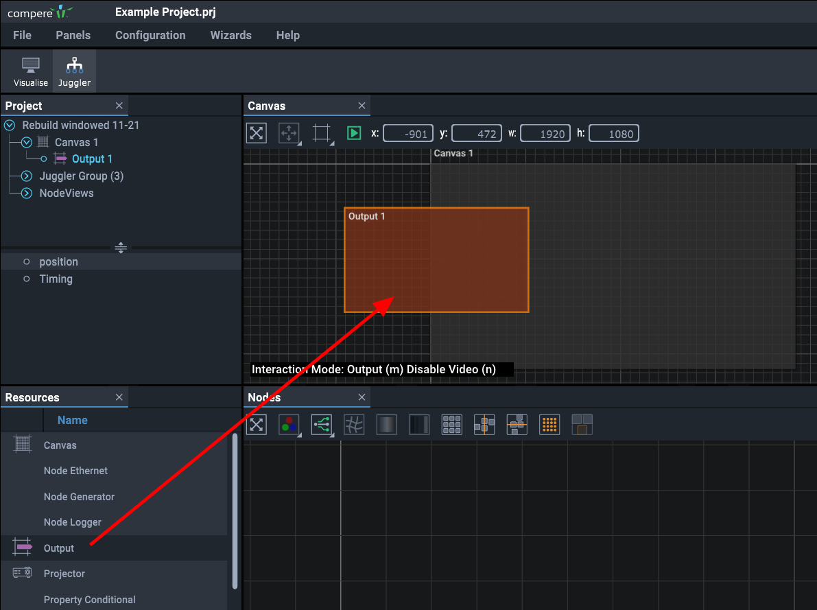
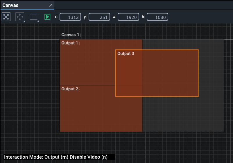
Canvas Outputs are the channels driven from Juggler transmit (Tx) ports that together will comprise your display area(s). They are sized to the physical pixel resolution of the output device. The EDID of Tx ports are set in the Juggler using Nodes View.
•Drag an Output from the Resources panel onto the Canvas.
Again, since it is selected it will have an orange bounding box.
The Output is now visible as a branch in the Project panel as a child to the canvas it was dragged onto. By selecting an Output in the Project panel, you can configure it in the Properties panel. Add all your Outputs in the same way:
Note how the position and dimensions of the selected object is shown in the toolbar.
•Change the Interaction Mode to ‘Output’ by pressing the ‘m’ key while in the Canvas assembly panel until it reads ‘Output’. The same toggle is available on the toolbar button or right-click menu as ‘Interaction Mode’. This enables direct selection by double-clicking, otherwise Outputs are selected in the Project panel as branches of the Canvas.
Move an Output around the assembly panel by selecting it, and holding the Shift key while dragging it. Hold Shift+Alt to snap the Output to Canvas edges or to other items in the panel. Alternatively, type in the position, with the dimensions, into the Output > position properties, or the toolbar fields.
Right click Canvas objects for the shortcut menu item ‘Move’, offering predefined positions and incremental adjustments:
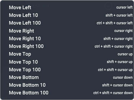
•The Up/Down/Left/Right arrow keys move the object towards that boundary of the canvas, 1 px at a time.
•Add Shift to move in 10 px increments.
•Add Ctrl+Shift to move in 100 px increments.
•Just add Ctrl to move straight to the boundary.
Window objects only:
•Shift+C will centre the item in the canvas.
•Shift+F will make the window fill the canvas.
When you move a canvas around in this panel (you can have more than one canvas), all the child outputs and windows move with it.
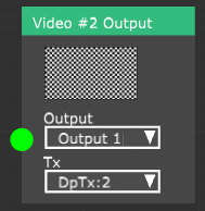
Apply an Output EDID. The properties of an output will adopt the EDID of the physical Juggler port to which it is assigned. When, in the Nodes assembly panel, you select a Canvas Output for a video channel output that has been assigned to a physical Juggler port, the Output here in the Canvas will be dynamically resized for you. In this next example in the Nodes panel, the Tx (physical output port) for channel 2 has been assigned to DisplayPort DpTx:2. By selecting ‘Output 1’ in the Output selector, the EDID for DpTx:2 will be applied to Canvas ‘Output 1’, and the Output in the Canvas panel will adopt the correct dimensions.
Edit the properties of an Output by selecting it in the Project panel to populate the Properties panel. Outputs and Windows are branches of the Canvas, which can be expanded or collapsed.
Output Properties
Name
Name the output logically and clearly. Multiple outputs are by default numbered sequentially. Names can also be changed in the Project panel by double-clicking the name there.
X Resolution / Y Resolution
Populated when using MPCDI.
Output > Position
X/Y, Width/Height
X and Y are the top-left co-ordinates in the Canvas. Width and height relate to the physical output device. Precisely position and size this Output in the Canvas.
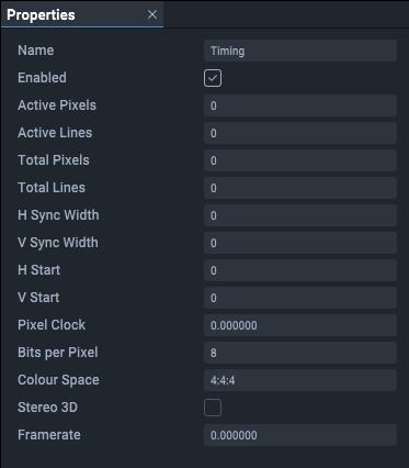
Output > Timing
Read only: provides information about this Canvas Output.
Page edited [d/m/y]: 26/09/2022
