Cables and Connectors
To ensure best performance from the server and compliance with relevant EMC regulations, this equipment should only be used with high-quality shielded data and signal cables.
Audio connectors (3.5 mm TRS / mini stereo jack)
These are the Realtek defaults as used in Delta Media Servers.

Double-click a connector’s graphic in Realtek HD Audio Manager to enable the auto pop-up dialog. This enables you to choose which device has been plugged in, for example to assign the blue socket to ‘Side Speakers Out’ rather than ‘Line In’.
Audio (stereo) TRS plug connections
Tip = Left channel
Ring = Right channel
Sleeve = Ground (common)
The audio channels as they appear in DeltaGUI are:
Delta channel |
Socket colour |
TRS connection |
7.1 speaker config |
5.1 speaker config |
|---|---|---|---|---|
1 |
Green |
Tip+Sleeve |
Front left |
Front left |
2 |
Green |
Ring+Sleeve |
Front right |
Front right |
3 |
Orange |
Tip+Sleeve |
Centre |
Centre |
4 |
Orange |
Ring+Sleeve |
Sub |
Sub |
5 |
Blue |
Tip+Sleeve |
Side left |
(unused) |
6 |
Blue |
Ring+Sleeve |
Side right |
(unused) |
7 |
Black |
Tip+Sleeve |
Rear left |
Rear left |
8 |
Black |
Ring+Sleeve |
Rear right |
Rear right |
Note: if one of the motherboard audio channels is assigned to LTC, that motherboard channel becomes unavailable for output.
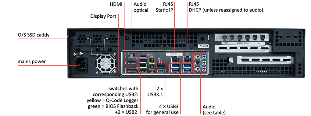
Delta Infinity Model 2021g
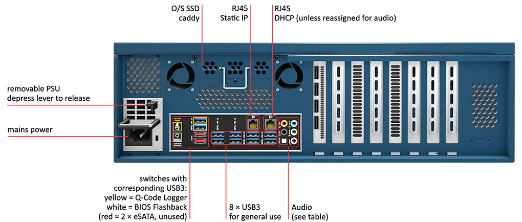
Delta Infinity (after May 2020, serial numbers from 4565)
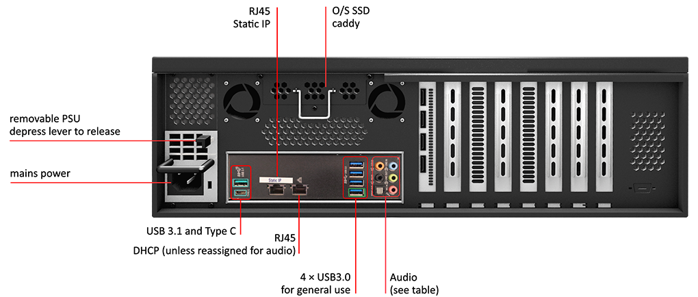
Delta Infinity (prior to May 2020, serial numbers to 4564)
Delta Infinity servers can be fitted with a redundant power supply. When fitted, the second is above the one shown here, and both operate in parallel. If one unit fails, there will be an audible warning, and the indicator light to the right of the failed socket will go out.
Condition |
LED status |
Sound |
|---|---|---|
Dual PSU, both good |
Both green |
none |
Dual PSU, one PSU failed |
Green-lit PSU good |
Audible alarm from the power distribution board |
One PSU unplugged |
This PSU unlit |
Audible alarm from the power distribution board |
One PSU removed |
N/A |
Audible alarm from the power distribution board |
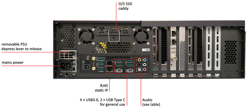
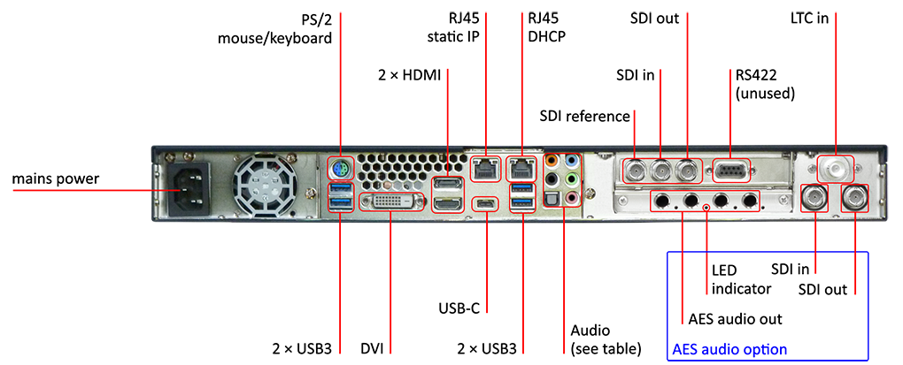
Delta Proton or Nucleus
Both models share the same motherboard connections. The illustration shows a Proton; Nucleus is a 3U unit, with a removable power supply and vertical cards, as the Infinity, above.
(Some connections may vary as motherboards change over time.)
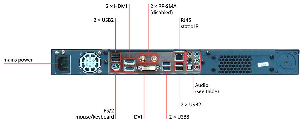
Delta NanoSDI
Delta NanoR
Delta Pico
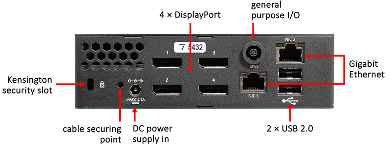
Pico low voltage power supply unit
The Pico is certified for use with the 19 V power unit supplied by 7thSense, rated at 100-240 VAC ~ 3-1.5 A, 60-50 Hz. The operating voltage for Pico is 12-19 VDC.
Pico NIC
On the rear right-hand side, the RJ45 port labelled ‘NIC 1’ is factory-set to a static IP and ‘NIC 2’ to DHCP. A label with this initial static IP address is provided on each unit.
From Delta 2.7, GPIO connectivity is enabled in DeltaGUI > Preferences > System. When checked, the GPIO driver is loaded when the Pico is started:
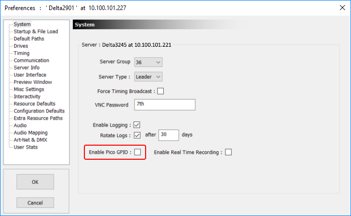
GPIO functionality takes up some CPU overhead. Disable it if not required, to maximise performance.
GPIO inputs and output functions are set by Delta External Controls, which are listed in DeltaGUI > Help > External Control, under GPIO Commands:
GPIO (PICO) COMMANDS |
|
GPIO_ID |
Flash the front LED green and orange to identify the server |
GPIO pin state |
Set the GPIO pin (1-4) to the desired state (0 = off, 1 = on) |
GPIO bitwise |
Set the GPIO pins to the desired bit pattern (0-255). 0 sets all pins low, 248 sets all available pins high, 176 sets pins 2, 3 high and 1, 4 low |
GPIO_SET_INPUT pin |
Set the GPIO pin (1-4) to be an input pin |
GPIO_SET_OUTPUT pin |
Set the GPIO pin (1-4) to be an output pin |
Physical connections
Pico servers with opto-isolated GPIO (serial numbers above 4600) These have a GPIO socket, wired as below, with 3 × I/O opto-isolated connections for use by Delta. |
Specification
•Voltage triggered level switching IO
•V (both Vcc and signal) max, 5 V. 3.3 V compliant so you can use either.
•Min Vcc is 3 V.
•I source 35 mA normal, 100 mA max.
•Max 400 pF output impedance.
•All data lines are weak pulled up to Vcc with 1 K resistors to allow for bidirectional switching.
