Projection Mode
The 3D Object/Surface
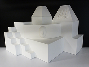 |
Multiple projectors can be used to display an image on a 3D surface that is designed to be viewed from a single design eyepoint. Essentially this creates a static situation where the object and projectors cannot change in relation to each other without losing alignment, and content will be absent from any other viewpoint, such as the reverse side of the object. Imagine rotating a cube in front of you: you will never be able to see more than three faces at once. This does not mean you cannot have design renders for other sides of an object, but that these are regarded as separate projections. Designer, projectors and the viewer are all observing the object from the same place, though the projectors can be offset. |
The 3D Model
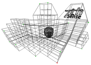 |
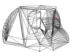
A 3D model is a system of co-ordinates (‘nodes’ or ‘vertices’) joined in a mesh. The co-ordinates take as their reference a zero-point (or origin) within (or outside) the model of the reference object. The model can be rotated and viewed from any angle, but when used for projection mapping, the designer will take a chosen viewpoint (or eyepoint) that ‘projects’ an orientation from which the object will be viewed. |
The 2D Media
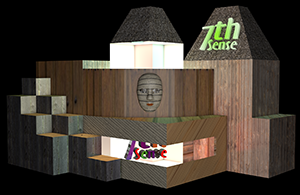 |
Because the designer’s reference point is the origin of the model, the media effectively represents what the origin of the model would see in a mirror. For better and sharper results, the media can be displayed over several projectors, and it may be better to split a complex mesh model into more manageable pieces for those projectors, but projection mode still assumes that the designer and viewer are both looking at the media-painted object from the same view of the model. |
Textured Mode
The 3D Object/Surface
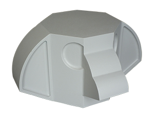 |
Just as the 3D model can be rotated and viewed from any angle, so the viewer can either move around the model, or the object can be rotated, and the media will ‘stick to’ and move precisely with the object. Here is a demonstration model of a totem head with easy-to-identify surfaces. |
The 3D Model
 |
The 3D model is constructed in the same way, but its entire external surface is notionally ‘peeled off’ or unfolded onto a flat surface. This surface is ‘painted’ by the designer to create specially rendered 2D media. Whilst the object and model are described in X × Y × Z axes, the surface is described in the 2D U × V axes, hence UV-rendered or mapped media. |
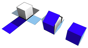 |
In this illustration a simple cube demonstrates the theory of what can be actually a more complex mapping, as in the ‘totem head’ example used here. |
The 2D UV-Mapped Media
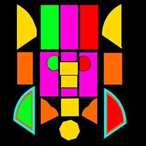 |
For the designer, all viewpoints now are perpendicular to the model/object surface, rather than, say an oblique view of the side of a cube. In textured mode, the characteristics of the mesh model surface are ‘baked’ into the flat media, which is then folded back onto the model in the projection. Compare this UV-mapped media frame with the one used above for projection mode. The top row of faces are projected on the other side of the object, either by rotating the object into projector view, or by providing all-round channel coverage. The reason this media does not look simply unfolded as in the cube above, is that this would create a lot of empty space in every frame. Instead, the elements are packed into the 2D space, with mapped coordinates that are used to place them on the target object or canvas. |
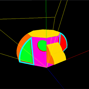 |
This is how the UV media looks in the Playback Window when ‘folded’ or positioned back onto the model, as seen from a single channel. The yellow lines show the model origin (X,Y,Z = 0,0,0); red, green and blue are the X, Y, Z axes. |