The Mesh Editor allows you to manipulate the mesh as a whole, per channel, by vertex or group of vertices, with control over the editing view. The X, Y, Z axes throughout are those based on the .obj model’s origin.
Even if you are not editing points, the mesh editor has settings for moving the mesh around in the GUI, with slider controls for Node Size and Mouse movement size.
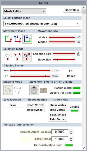
Movement Plane
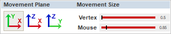
Select which 2D plane (axis pair) in which you want to move selected vertices, in the overall 3D space.
Movement Size
The Vertex slider controls sensitivity of selected vertex movement, using Ctrl+arrows. The Mouse slider controls the speed at which the mouse drags the mesh around in the GUI.
Drawing Mode

These options enable you to see the entire mesh, or focus on the foreground only. The result will depend in part on the way the mesh has been constructed.
Movement: World or Per Channel
Choose whether you want to manipulate the mesh for a particular channel only, or for all channels (World view). Per channel is generally best for small adjustments, and World if there is a significant error in the media across the whole object. These edits are overlaid on the .obj mesh and will be saved as separate .vto files. The Disable buttons switch the adjustment overlays off and on without resetting the model.
Selection Mode
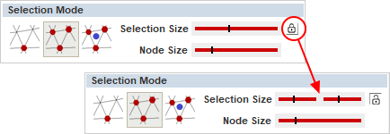
Vertices can be selected either to reposition them, or to change their visibility (as in the oblique faces of our object example above). Select a single vertex to move it, or a group of vertices, or where a set of linked vertices has been constructed in the .obj file, select the group.
The group selection area finds all vertices within an XY window as seen from the current viewpoint in the GUI, not relative to the size of the obj mesh. The size of this window can be controlled by the size slider. Click the lock button for separate X and Y axis sizes. Selection includes all vertices in this rectangle, in all planes. Add more vertices to the group selection with Ctrl+left click. Near or far vertices can be excluded by working in a clipping plane (see below). For multiple selection of individual vertices, use a very small group area.
In this example: red points are a selected group with equal XY selection. Green shows the mouse hovering over another group with a limited X axis and mid-range Y (see settings on the right).

Moving points: Once selected, all red nodes can be moved around en bloc using Ctrl+arrows. For finer movement, use Ctrl+Shift+arrows. Movement is along the X, Y, Z axes of the .obj file, based on the object origin. Selected vertices or the whole model can be reset using the Reset buttons (bottom right).
Moving nodes around
Whenever groups of connected nodes are moved, this inevitably distorts the surrounding mesh. A mesh that is not an accurate representation of the real world can, to some degree, be pulled into position, but there are limits beyond which making one part fit makes another worse.
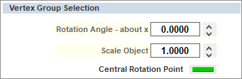
Vertex Groups
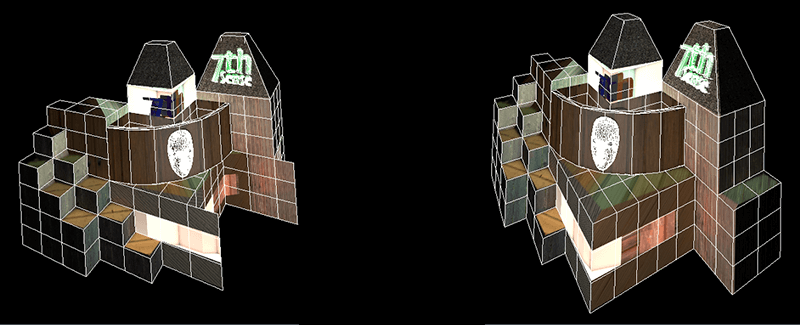
In complex models it is helpful to construct the .obj file out of groups of vertices where the groups are not connected directly to each other: for example, the detailed face illustrated above is separable. In these circumstances, the separable section of linked vertices can be selected by use of the third mesh selector in Delta (the one with the blue dot): the ‘vertex group selection’. The separable part can now be manipulated, to move it, or rotate it on any axis about a selected point, or its median point.
In the illustration below, the face element from the front of the building has been selected with a single click because it forms a vertex group, unconnected to the main building. Lateral movement is as elsewhere using Ctrl+arrows, or Ctrl+Shift+arrows (finer) according to the movement size set in the editor panel, and the selected movement plane axes.
Please note that depending on the complexity of the vertex group being manipulated, this can be very demanding of DeltaGUI.

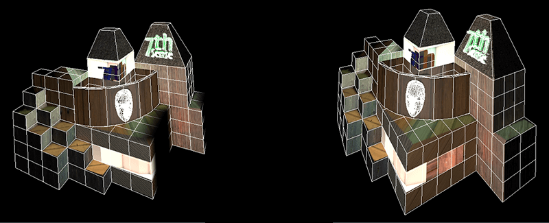
Rotation is available, again in the selected movement plane axis, either about the central rotation point, or a selected point (click the green button to switch this).
The vertex group can also be scaled about the same point, increasing or decreasing all vertex separations proportionately. Here we can see that by selecting the X-Y movement plane, rotation will be about the Z-axis:
These adjustments can be seen in the editing screen above.
What moves? If the mesh and media are texture-mapped, the media will follow the moved element, so the media can be adjusted to a real-world object that does not quite match. If the media is not texture-mapped (i.e. projection mode), then it will continue to be projected in situ. This is not the same as warping the mesh. |
Hiding points: There are two ways to affect the projected display of selected parts of the media: Show/Hide and Black/Paint. Hiding a group removes all edges joined to the selected vertices, and enclosed faces. Single vertex selection is not useful for hiding, but a single vertex in a small group may be. In the example below, per channel selection has been made on the oblique sides in channel 1 (left), to be filled exclusively by channel 2 (right). In the first Playback Window illustration below, Hide removes faces from display, in the second, Black fades it out, similar to blending.
Note how vertex selection has not included the vertical edges required by channel 1.
Compare this with adding a blend, and the need to preserve display on edges; a blend may fade out more than you want. Blends are more suitable for textured mode.
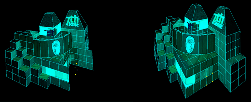
When mesh editing, Playback will show in blue-green colour, indicating that it is in low-performance mode. Restore this by going back to channel mode.
Clipping Planes
These contain your view for selection, between Near and Far planes. Use the Fit button to set the range to the size of your mesh, otherwise the mesh can be too small a part of the maximum available range, and disappear from view. In this example, clipping planes have been used to limit selection to points on the facing wall in the above illustration:

Save Meshes
You can save changes to the mesh simply by using File > Save As (and then Save to save further changes). This saves the original .obj file, together with .vto files containing adjustment instructions. Every time the mesh is used for a show, these instructions will be applied. ‘World’ and ‘Per Channel’ change files are created separately.

To remove the changes, returning to the original mesh alone, simply reset in the GUI or delete the .vto files here. If you have ‘Sync Mesh Files from Server’ ticked in the Mesh selection screen, the files will also be copied over automatically to the GUI.
The mesh editor, however, also allows you to ‘bake’ the changes into either a new single revised ‘world’ .obj file, or a new .obj per channel. Changes cannot be reset in a ‘baked’ file.

Reset Meshes
Note that resetting the whole model sets all vertices back to their original positions in their .obj file. If you have loaded an .obj file that has associated .vto files, resetting the model removes the .vto amendments from view, and if then saved, the .vto files are removed from the C:\Meshes directory. If in doubt, and you want to compare before and after adjustments, use the Disable button instead.
Page edited [d/m/y]: 01/07/2021