| Name: | StagetechRigging System |
| Version: | 6.7.2 |
| Available for: | Manager V7 and Manager V6 (Lite & Pro), Showmaster (Mini, ST, Pro, LE, XS & iPro) |
| Limitation In: | |
| Device Brand: | Stagetech |
| Positrack Compatible: | No |
| Resourcestype: | UDP/IP |
Overview
The Stagetech Rigging System (SRS) is a software implemented in PLCs such as the Simotion from Siemens by the Stagetech company. This MxM can control multiple SRSs through Ethernet. The MXM controls scenic elements on the SRS, these elements are called “axis”.
The MXM also controls output pins on the SRS (i.e relay like outputs) and monitors input pins.
MxM Installation
The computer running Medialon Manager and the PLC running the SRS must be in the same network.
The SRS broadcasts messages through UDP. So in order to receive these messages, an adapter with an address in the range 10.0.3.x must be specified on the computer. The MXM has a log trace mechanism based on an ODBC database connection.
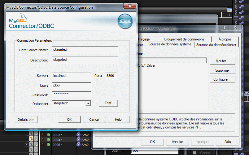
So, in order to use this database, an ODBC alias must be created to this database so that it can be specified when creating the device in Medialon Manager (the ODBC setup window can be accessed through the device setup dialog window).
Device Setup
This MxM manages two types of devices: “main” devices and “axis only” devices.
The first device created on a specified SRS is a “main” device, the following devices created are “axis only” devices:

If any SRS is present on the network, click the “Scan” button, and the MxM will communicate with the SRS found and fill the informations for I/Os and axis:

The SRS PLC has a parameter dialog:
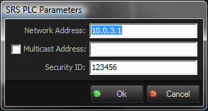
Enter the address of the PLC.
If the model streams his parameters on a multicast address (see Stagetech documentation), check the multicast box and enter the multicast address.
Enter the security code, as specified by Stagetech, to prevent the reception of invalid frames on UDP.
If no SRS is present, enter the I/Os and axes manually.
Note that the setup of the I/Os is available only for the “main” device.
I/Os and axes can be added, deleted and edited with the Add, Delete and Edit buttons:
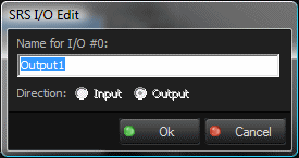
When an I/O is detected by the scan, it is called “output” or “input” depending on the direction of the I/O. It can be renamed, and this name can be then used in the “SetOutput” command (see the command list below).
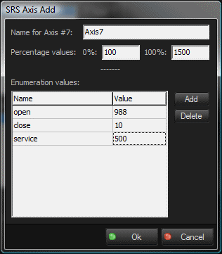
In the axis setup window, the name of the axis and several other parameters can be defined.
The percentage values represent the value in millimeters for 0% and 100%. When these values are defined for an axis, they can be used in the commands, by specifying a percentage for the position of the axis (see the command list below).
A list of enumeration values can be created for each axis. These values can also be used in the commands, by specifying a name for the position of the axis (see the command list below).
For information purpose, the maximum values for the speed, the acceleration, and the deceleration are displayed in this window.
The “Database Setup” button (available only for the “main” device), brings up a window for specifying the parameters of the ODBC alias pointing to the database used for logging purpose:
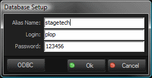
In this window, the “ODBC” button opens the ODBC setup dialog box:
Device Commands
The commands marked with * are available only for the “main” device.
Store
To store moving parameters into one or several axes. The axis does not move (the “Start” command must be sent in order to move the axis with the specified parameters). This command is useful for performing sequential moves. Several positions can be stored in different memories of the SRS and the range can be called with the “Start” command.
- Axis List: [String] List of the axes concerned by the command. It can be only one axis, or a list of axes. In the list, the names must be separated by commas. The names can be the index of the axis (1 based) or the names specified in the device setup. A wizard is available for the choice of axes. Any axis specified that does not belong to the device will be ignored.
- Position: [String] Target position that the axis has to reach. It can be a number, positive or negative, representing a count of millimeters. It can be a number followed by the % sign, and in this case it represents a percentage (this will work only if the 0% and the 100% have been defined for this axis in the device setup). It can be a litteral position as specified in the position enumeration of this axis. A wizard is available with the enumeration of the positions in case of multiple axis, all the positions are listed, and the position that don’t belong to an axis will be ignored when the command will be sent.
- Speed: [Integer] Speed to reach the target position (mm/s). A wizard is available for calculating speed, acceleration and deceleration, based on positions and times.
- Acceleration: [Integer] Acceleration parameter (mm/s). A wizard is available for calculating speed, acceleration and deceleration, based on positions and times.
- Deceleration: [Integer] Deceleration parameter (mm/s). A wizard is available for calculating speed, acceleration and deceleration, based on positions and times.
- Memory: [Integer] Memory slot where to store the parameters in the SRS. This number will be used afterwards in the “Start” command. Maximum memory number is 99.
Start
Start the motion(s) with the parameters previously stored by the “Store” command.
- Axis List: [String] List of the axes concerned by the command. It can be only one axis, or a list of axes. In the list, the names must be separated by commas. The names can be the index of the axis (1 based) or the names specified in the device setup. A wizard is available for the choice of axes. Any axis specified that does not belong to the device will be ignored.
- From Memory: [Integer] Number of the first parameter memory to use for moving.
- To Memory: [Integer] Number of the end parameter memory to use for moving. The SRS will perform the moves sequentially.
TimeGoto
This command will perform a “Store” immediatly followed by a “Start”.
It uses times for the speed, acceleration and deceleration parameters.
- Axis List: [String] List of the axes concerned by the command. It can be only one axis, or a list of axes. In the list, the names must be separated by commas. The names can be the index of the axis (1 based) or the names specified in the device setup. A wizard is available for the choice of axes. Any axis specified that does not belong to the device will be ignored.
- Position: [String] Target position that the axis has to reach. It can be a number, positive or negative, representing a count of millimeters. It can be a number followed by the % sign, and in this case it represents a percentage (this will work only if the 0% and the 100% have been defined for this axis in the device setup). It can be a litteral position as specified in the position enumeration of this axis. A wizard is available with the enumeration of the positions in case of multiple axis, all the positions are listed, and the position that don’t belong to an axis will be ignored when the command will be sent.
- Duration: [Time] Time duration to reach the target position.
- Acceleration Duration: [Time] Time duration of the acceleration within the global duration time.
- Deceleration Duration: [Time] Time duration of the deceleration within the global duration time.
- Memory: [Integer] Memory emplacement to use for the command. Maximum memory number is 99.
SpeedGoto
This command will perform a “Store” immediatly followed by a “Start”.
It uses integer values for the speed, acceleration and deceleration parameters.
- Axis List: [String] List of the axes concerned by the command. It can be only one axis, or a list of axes. In the list, the names must be separated by commas. The names can be the index of the axis (1 based) or the names specified in the device setup. A wizard is available for the choice of axes. Any axis specified that does not belong to the device will be ignored.
- Position: [String] Target position that the axis has to reach. It can be a number, positive or negative, representing a count of millimeters. It can be a number followed by the % sign, and in this case it represents a percentage (this will work only if the 0% and the 100% have been defined for this axis in the device setup). It can be a litteral position as specified in the position enumeration of this axis. A wizard is available with the enumeration of the positions in case of multiple axis, all the positions are listed, and the position that don’t belong to an axis will be ignored when the command will be sent.
- Speed: [Integer] Speed value in millimeter per second.
- Acceleration: [Integer] Acceleration value in square millimeter per second.
- Deceleration: [Time] Deceleration value in square millimeter per second.
Stop
To stop the motion(s) of the specified axes.
- Axis List: [String] List of the axes concerned by the command. It can be only one axis, or a list of axes. In the list, the names must be separated by commas. The names can be the index of the axis (1 based) or the names specified in the device setup. A wizard is available for the choice of axes. Any axis specified that does not belong to the device will be ignored.
StopAll*
To stop all the motions of all axes.
SetOutput*
To change the value of outputs.
- Output: [String] List of the outputs concerned by the command. It can be only one output, or a list of outputs. In the list, the names must be separated by commas. The names can be the index of the output (1 based) or the names specified in the device setup. A wizard is available for the choice of outputs.
- Status: [Enum] Value of the new status for this output.
- “On”: sets the output on
- “Off”: sets the output off
- “Flash”: flashes the output with a period based on the following parameters
- High Time: [Time] Time the output is held on in flash mode.
- Low Time: [Time] Time the output is held off in flash mode.
GetConstant*
To read maximum values of an axis.
- Axis: [Integer] Iindex of the axis (1 based).
- Constant Index: [Enum] The constant to read.
- “Max Speed”: maximum value for the speed.
- “Max Acceleration”: maximum value for the acceleration.
- “Max Deceleration”: maximum value for the deceleration.
- “Max Limit”: maximum value for the position of the axis set inside the SRS software (0 if no limit).
- “Min Limit”: minimum value for the position of the axis set inside the SRS software (0 if no limit).
- Return Value: [Integer] Specify the variable that will receive the value in return.
Speed
Change the speed of the current motion on the fly.
- Axis List: [String] List of the axes concerned by the command. It can be only one axis, or a list of axes. In the list, the names must be separated by commas. The names can be the index of the axis (1 based) or the names specified in the device setup. A wizard is available for the choice of axes. Any axis specified that does not belong to the device will be ignored.
- Speed Override: [Integer] Value of the new speed in percentage of the speed specified in the “Store” command. The range is between 1 and 200 %.
Device Variables
Status
[Enum] Current status of the device communication.
- “NotOnLine”: No communication with the SRS
- “Ready”: Ready to communicate
- “Error”: An error has occured (see detailed ErrorMessage variable).
ErrorMessage
[String] Current error message.
I/O Names
(count depending on the count of I/O specified in the setup)
[Integer] Current status of the I/O (0 or 1).
AxisName_Status
(count depending on the count of axis specified in the setup)
[Enum] Current status of the axis.
- “NotOnLine”: This axis does not exist or the SRS is not on line
- “Unknown”: Status is unknown
- “Ready”: The axis is ready to receive command
- “Busy”: The axis is busy (after command reception)
- “Moving”: The axis is moving
- “Delaying”: The axis is waiting
AxisName_Position
(count depending on the count of I/O specified in the setup)
[Integer] Current position of the axis.
AxisName_ErrorMessage
(count depending on the count of I/O specified in the setup)
[String] If the axis is on error, this variable will contain the number of the error followed by the litteral error message as specified by Stagetech.
AxisName_UltimateLimit
(count depending on the count of I/O specified in the setup)
[Integer] Will be 1 if the axis has reached the ultimate limit.
AxisName_HighInitialLimit
(count depending on the count of I/O specified in the setup)
[Integer] Will be 1 if the axis has reached the high initial limit.
AxisName_LowInitialLimit
(count depending on the count of I/O specified in the setup)
[Integer] Will be 1 if the axis has reached the low initial limit.
AxisName_CrossGroove
(count depending on the count of I/O specified in the setup)
[Integer] Will be 1 if the axis cross groove status is on.
AxisName_SlackRope
(count depending on the count of I/O specified in the setup)
[Integer] Will be 1 if the axis slack rope status is on.
AxisName_Estop
(count depending on the count of I/O specified in the setup)
[Integer] Will be 1 if the axis estop is on.
Revisions
V 1.0.0
- Fixed: When an axis device activity is disabled, the commands are not sent, and the variables are not updated. When a main device activity is disabled, no commands are sent and no variables are updated to any axis depending from this main device.
V 1.0.1
- Internal Changes.
V 1.0.2
- Support for Showmaster Pro.
V 6.0.0
- Modified: Support of Manager V6/Showmaster V2.
V 6.0.1
- Fixed: Setup dialog doesn’t open on the correct screen on a multi-screen configuration.
V 6.0.2
- Fixed: Device variables are not reset after a project load (Requires Manager 6.0.3+).
V 6.1.0
- Added: Support for Showmaster LE & Showmaster XS platforms.
V 6.1.1
- Fixed: The MXM does not appear as certified under Manager.
V 6.1.2
- Fixed: The Setup dialog box is not always fully visible at the device creation time.
V 6.1.3
- Fixed: MXM Commands may sometimes hang Manager/Showmaster while the command being executed.
V 6.7.0
- Improved: Support for High DPI displays (require Manager 6.7.0+ or Showmaster Editor 2.7.0+)
- Changed: Compatibility for Manager 6.7.0 and Showmaster Editor 2.7.0
