| Name: | Medialon Low Level Communicator |
| Version: | 6.7.2 |
| Available for: | Manager V7 and Manager V6 (Lite & Pro), Showmaster (Mini, ST, Pro, LE, XS & iPro) |
| Limitation In: | Showmaster Mini |
| Device Brand: | Medialon |
| Positrack Compatible: | Partially |
| Resources type: | Serial, MIDI, TCP/IP Network, UDP/IP Network |
Overview
The Low Level Communicator MxM is a low level but powerful MxM.
It is a low-level MxM because it is not dedicated to a special device and is able to use many raw communication protocols.
But it is powerful for two reasons.
Five types of communication available
- Serial
- TCP/IP Client
- TCP/IP Server
- UDP/IP Client-Server
- MIDI
Custom drivers
The programmer can write its own set of commands, create monitoring variables linked to the reception of specified frames, and much more, in order to write drivers dedicated to specified devices and projects
Important Note 1: When this MXM is used with Showmaster and when a TCP/IP server or UDP/IP device is used, the external connection needs to be setup to the address of Medialon Showmaster Editor host during the programming process. When the programming process is completed and Showmaster Editor has been disconnected, the external connection can be setup again to the address of Showmaster.
Important Note 2: The representation of a hexadecimal value in this document uses the scheme !XX when XX are the two digits of the hexadeciaml value. This representation takes place of the other representations which can be found such as XXh or 0xXX.
MxM Installation
No specific installation is required.
Device Setup
At the creation of the device, a setup dialog with seven main pages box pops-up.
These seven main pages are: Type, Frames, Checksum, Commands, Answers, Monitoring, Automation. All these parameters are saved with the Manager project, as all other MXMs, but they also can be saved in separate drivers files. These drivers files can be re-used in other projects ( see DRIVERS section).
Type
Five type of communication are available: serial, TCP/IP client, TCP/IP server, UDP/IP Client-Server, MIDI, which correspond to five different parameters pages (TCP/Server is not available in lite version).
Serial parameters

COM Port: The number of the com port to use with this device. If this port is used by another device, the name of the device is written between brackets within the number of the port. If a message says “Impossible to open this port” at the time you close the dialog box or at the startup of the device, it may be because this port has been opened by another application or driver.
BaudRate, Stop bits, Data bits, Parity: The setup at which the port must run at the startup of the device.
DTR, RTS: These two signals are present in the RS socket. In some protocol, these signals are used to detect the start of a frame, or to say if the device can send or receive.
Full Duplex / Half Duplex: Full duplex is used with separate lines for sending and receiving. Half duplex is when the same line is used alternatively for both.
Break character: Break character is the character that will be set in the frame for sending a break (low status) on the serial line.
Break time: The break time is the time that this break will last.
TCP/IP Client parameters
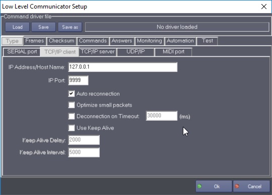
IP Address/Host Name: IP Address or Host Name of the server on which this client will connect.
IP Port: Port on which this client will connect.
Auto reconnection: When this option is checked, the MxM will periodically try to reconnect if it looses the connection.
Optimize small packets: Check this option if you send small frames and if you want to increase the speed of the transmitting. It will set the TCP_NODELAY option in the Network system. Enabling the TCP_NODELAY option disables the TCP Nagle Algorithm (and vice versa). The Nagle algorithm (described in RFC 896) is very effective in reducing the number of small packets sent by a host by essentially buffering send data if there is unacknowledged data already “in flight” or until a full-size packet can be sent. However, for some applications this algorithm can impedeperformance, and TCP_NODELAY can be used to turn it off. These are applications where many small messages are sent. Application writers should not set TCP_NODELAY unless the impact of doing so is well-understood and desired, since setting TCP_NODELAY can have a significant negative impact of network and application performance.
Use Keep Alive: This option allows to automatically check if the session is still alive when there is no communication. It is useful to detected unplug cables or any link problem between the client and the server. However, the Keep Alive mechanism is unfortunately not supported by all the devices, therefore in some cases this mechanism may not work at all or may generate “false” disconnection. It is recommended to either check if both the client machine and the server support this mechanism or to conduct preliminary tests before entering in production.
Delay: specifies the timeout, in milliseconds, with no activity until the first keep-alive packet is sent. Interval: specifies the interval, in milliseconds, between when successive keep-alive packets are sent if no acknowledgement is received. The number of retries when there is no acknowledgement is 10 (this is a fixed value). As a consequence, the total delay in case of problem is Delay + (Interval * 10)
Deconnection on Timeout (false by default): When the Timeout is reached, it disconnects the TCPClient. Then if the auto-reconnection is enabled, the TCPClient will attempt automatically to reconnect. It’s recommended to enable this option when at least one Monitoring command is defined or if the device is supposed to send data regularly to the MXM device.
Deconnection on Timeout (30000ms by default): The Timeout is reached by the TCPClient when nothing has been received during the specified period. The counter is started / reseted each time that a data is received by the TCPClient. It allows to detect if Ethernet cable has been removed or if the network is not working anymore. The Timeout value must be higher than the maximum delay required by the device to process a command and send back its result. It should also be higher than the interval between two commands.
TCP/IP Server parameters
(TCP/Server is not available in lite version )

Port: Port on which this server will listen.
Adapter for reception: If “all”is checked, the server will listen on all the network adapters present on the computer, if not, it will listen on the specified adapter.
Optimize small packets: Check this option if you send small frames and if you want to increase the speed of the transmiting. It will set the TCP_NODELAY option in the Network system. Enabling the TCP_NODELAY option disables the TCP Nagle Algorithm (and vice versa). The Nagle algorithm (described in RFC 896) is very effective in reducing the number of small packets sent by a host by essentially buffering send data if there is unacknowledged data already “in flight” or until a full-size packet can be sent. However, for some applications this algorithm can impedeperformance, and TCP_NODELAY can be used to turn it off. These are applications where many small messages are sent. Application writers should not set TCP_NODELAY unless the impact of doing so is well-understood and desired, since setting TCP_NODELAY can have a significant negative impact of network and application performance.
Use Keep Alive: This option allows to automatically check if the client session is still alive when there is no communication. It is useful to detected unplug cables or any link problem between the client and the server. However, the Keep Alive mechanism is unfortunately not supported by all the devices, therefore in some cases this mechanism may not work at all or may generate “false” disconnection. It is recommended to either check if both the client machine and the server support this mechanism or to conduct preliminary tests before entering in production.
Delay: specifies the timeout, in milliseconds, with no activity until the first keep-alive packet is sent. Interval: specifies the interval, in milliseconds, between when successive keep-alive packets are sent if no acknowledgement is received. The number of retries when there is no acknowledgement is 10 (this is a fixed value). As a consequence, the total delay in case of problem is Delay + (Interval * 10)
UDP/IP parameters
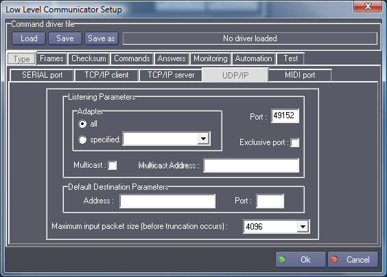
Maximum input packet size: This setting is low by default in order to minimize resources usage. It can however be raised in order to receive bigger UDP frames, up to a maximum of approximatively 64KB. All frames above this size will be truncated when received.
Adapter for reception: If “all”is checked, the MXM will listen on all the network adapters present on the computer, if not, it will listen on the specified adapter.
Port: Port on which the MXM will listen.
Exclusive port: If checked, the port will not be shared, no other application can simultaneously open it on the same computer.
Multicast: Check this option if you want to specify a multicast address for listening. (It is the responsibility of IANA to manage the multicast address space [27, 1]. Multicast addresses range from 224.0.0.0 through 239.255.255.255. The address 224.0.0.0 cannot be assigned to any group since it is reserved. These addresses are permanent in the sense that it is the address, not the membership of the group, which always exists [15]. A permanent group may have any number of members at any time, which can be even zero. Other multicast addresses are temporary in nature and the groups which they represent are called transient multicast groups).
Default Destination Parameters: This is where you can specify a default address and a default port where udp frames will be sent by the monitoring process( see the creation of monitoring parameters ), and by the “Send Frame” command.
UDP/IP receiver behavior on Showmaster:
When the UDP/IP mode is used under Showmaster as a receiver, the following considerations are important:
UDP client application’s target addresses (i.e Showmaster) are not automatically redirected to Showmaster Editor when programming mode is activated, this operation must be done manually on the client application side.
TCP client application’s target addresses must be set to point to the Showmaster in Running mode (stand alone Showmaster).
TCP client application’s target addresses must be set to point to the computer running Showmaster Editor in Programming Mode (when Editor is connected to the Showmaster).
MIDI parameters
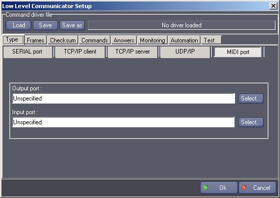
Output port: Port on which the MXM will send MIDI frames.
Input port: Port on which the MXM will receive MIDI frames.
Frames

Output: Parameters used in the format of the output frames.
Checksum character:Checksum character is the character that represents the checksum in the frame and it will be computed before sending the frame.
Hexadecimal character: This is the ascii character used for sending an hexadecimal character. For example, if the “!” is used, you can write !0A!0D for sending a carriage return and a line feed.
Decimal character: This is the ascii character used for sending a decimal character. For example, if the “ &” is used, you can write &255 for sending this upper ascii byte.
Input: These parameters define the validity of an input frame. This validity is the one taken into consideration for the device variable FramesCount (see below) to indicate that valid frames have been incoming.
Count of bytes: This is the count of bytes that the device waits for. If ending or header character are filled (see below), this parameter can be null: in this case all the bytes between ending character and(or) header character fills the frame.
Timeout: This is the maximum time that can occur between two bytes of a same frame. Each time this value is over, the device empties its internal counter and waits for the first byte of a frame. If this value is set to zero, the mechanism is disabled. WARNING: if the timeout is set to zero and the count of input bytes is also set to zero, the input frame can become huge if it is not read out by “Get frame”.
Header character: When this character is received, it is considered to be the first character of a frame. You can use the hexadecimal character here (for example !02).
Ending character: When this character is received, it is considered to be the last character of a frame. You can use the hexadecimal character here (for example !03).
Perform checksum verification: If this option is enabled, the checksum is calculated each time a frame is considered to be valid by the previous parameters. The byte of the checksum must be equal to the checksum byte before a frame is considered to be definitly valid.
Convert only the non-literal bytes to the hexadecimal format: If a non literal byte (ascii value < 31 and > 127) is received it is converted to the hexadecimel format, using the “hexadecimal character” entered before.
Convert all the bytes received to the hexadecimal format: All the bytes received are converted to the hexadecimel format, using the “hexadecimal character” entered before.
Keep the original values: When checked, nothing is converted.
Store frames: When checked, all the frames received are stored and you can fetch them with the “Get frame” command. When unchecked, only the last frame is stored.
Max stored frames: This option is available only when “Store frames” is enabled. It allows defining the maximum of storable frames. By default, its value is 250. It is not possible to set this value to 0 or lower.
Character replacement
This section lists the character that must be replaced in the frames before sending and replaced back the other way upon reception.
Excluded/Replaced: The left list contains the excluded characters, the right list contains their replacement. On output excluded characters are replaced by the corresponding string, and on input the replacement string is transformed back to the original characters.
Not for header/ending character: Check this box if you don’t want to aply the replacement to the firt and to the last character of the frame.
Checksum before replacement: Tells if the checksum (if enabled) must be calculated before or after the character replacement phase. If the checksum occurs before the replacement, then it is computed on the original string and if the checksum value happens to fall on a special character, it will also be replaced.
If the checksum occurs after replacement, it is computed on the replaced string, and the checksum value itself is not replaced if falling on a special character.
Checksum
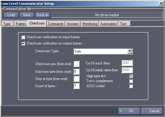
These parameters define the checksum verification options. They work together with the “checksum character” and “checksum before replacement” options of the “Frames” config tab.
Checksum check can be enabled on input or output frames, or on both. The first occurrence of the “checksum character” will be replaced upon sending or reception by the appropriate checksum, computed using the following options:
Checksum Type: This allows to select the type of checksum of the frame:
Sum: This checksum is the sum of all the bytes between the byte indicated by ‘Start from byte’ parameter and the byte before the checksum character or indicated by ‘Stop at byte’ parameter.Note: ‘Checksum pos’ parameter is not used.
Xor: This checksum is the result of a XOR operation of all the bytes between the byte indicated by ‘Start from byte’ parameter and the byte before the checksum character or indicated by ‘Stop at byte’ parameter.Note: ‘Checksum pos’ parameter is not used. Note: ‘Count of Bytes’ parameter is always 1 with this type.
Or: This checksum is the result of a OR operation of all the bytes between the byte indicated by ‘Start from byte’ parameter and the byte before the checksum character or indicated by ‘Stop at byte’ parameter.Note: ‘Checksum pos’ parameter is not used. Note: ‘Count of Bytes’ parameter is always 1 with this type.Note: This is a very inefficient checksum but it is present in some protocols.
Crc16: This checksum is the two bytes result of a polynomial calculation between the byte indicated by ‘Start from byte’ parameter and the byte before the checksum character or indicated by ‘Stop at byte’ parameter. Note: CRC stands for Cyclic Redundency Check). Note: ‘Checksum pos’ parameter is not used.
Level Control System 7 Bit Checksum: This type of checksum is used by the Level System Control Matrix3/Matrix4 protocol.
Alcorn Mc Bride AMINet: This type of checksum is used by the Alcorn Mc Bride AMINet UDP protocol (for the DVM4).
Start checksum from byte (from start): It indicates at which byte of the frame the checksum computation must start (zero indexed). If this value is not set, the computation starts from the first byte.
Stop checksum at byte (from end): It indicates at which byte of the frame the checksum computation must stop (zero indexed). If this value is not set, the computation stops just before the checksum byte.
Checksum pos: It indicates at which byte of the frame the checksum byte is located (zero indexed).
- Crc16 mask: CRC uses a polynome definition for the computation, this parameter indicates which members of that polynome are used to compute the CRC. Each bit corresponds to a member of the polynome (bit is 1 if the member is present otherwize bit is 0) and is given low bits first. Generally a CRC16 polynome is expressed with x^16 member which is hidden for the CRC16 mask value. Typical polynom (also known as CRC16-ANSI) is expressed as
x^16 + x^15 + x^2 + x^0. To compute the CRC16 mask value, the polynome must be expressed low bits first (as mention above) with the x^16 member hidden such asx^0 + x^2 + x^15, which in terms of mask means1010 0000 0000 0001or!A0!01. Examples of polynome/mask:- CRC16-ANSI: Polynom:
(x^16 +) x^15 + x^13 + x^0, Mask:!A0!01. This value is the default value and is commonly used in the industry. - CRC16-CCITT (Kermit): Polynom:
(x^16 +) x^12 + x^5 + x^0, Mask:!84!08. - CRC16-DNP: Polynom:
(x^16 +) x^13 + x^12 + x^11 + x^10 + x^8 + x^6 + x^5 + x^2 + x^0, Mask:!A6!BC. - Any other value can be used accordingly to the device protocol definition. Please refer to the device protocol documentation.
- CRC16-ANSI: Polynom:
Crc16 initial value: This parameter indicates a constant value used to initialize the computation registers:
!00!00 (default value) is commonly used in the industry.
The CCITT defines the value !FF!FF.
Any other value can be used accordingly to the device protocol definition. Please refer to the device protocol documentation.
- Crc8 mask:
CRC uses a polynome definition for the computation, this parameter indicates which members of that polynome are used to compute the CRC. Each bit corresponds to a member of the polynome (bit is 1 if the member is present otherwize bit is 0) and is given low bits first. Generally a CRC8 polynome is expressed with x^8 member which is hidden for the CRC8 mask value. Typical polynom (also known as CRC8-CITT) is expressed as
x^8 + x^2 + x^1 + x^0. To compute the CRC8 mask value, the polynome must be expressed low bits first (as mention above) with the x^8 member hidden such asx^0 + x^1 + x^2, which in terms of mask means1110 0000or!E0. Examples of polynome/mask:- CRC8-CCITT: Polynom:
(x^8 +) x^2 + x^1 + x^0, Mask:!E0. - CRC8-DALLAS: Polynom:
(x^8 +) x^5 + x^4 + x^0, Mask:8Ch. This value is the default value. - CRC8-W-CDMA: Polynom:
(x^8 +) x^7 + x^4 + x^3 + x^1 + x^0, Mask:!D9. - Any other value can be used accordingly to the device protocol definition. Please refer to the device protocol documentation.
- CRC8-CCITT: Polynom:
- Crc8 initial value:
This parameter indicates a constant value used to initialize the computation registers:
- !FF (default value) is defined by the CCITT and DALLAS.
- Any other value can be used accordingly to the device protocol definition. Please refer to the device protocol documentation.
High byte first: When checked the order of the two bytes resulting of the Crc16 is high-low, when not checked it is low-high.
Two’s complement: A (NOT+1) operation is performed on the checksum byte. (also explained as 256 minus the value ).
ASCII coded: The result of the operation is changed into ASCII characters. Important note: if the size of the checksum is set to 1, the “ASCII coded” operation will create two bytes, if the size of the checksum is set to 2, the “ASCII coded” operation will create four bytes. For example, with a size of 1 and a checksum result of 110 (in decimal) the two bytes will be the ASCII character “6” and “E”.
Count of bytes: The count of bytes of the checksum: it is usually 2 for the CRC16 checksum and 1 for the others.
Commands
The commands created in this section are added to the device command set. These commands can contain parameters where variables can be used.
Important Note: the name of a command fully identifies the command, thus renaming a command must be processed with care. As an example: if the “Play” command of a command driver is used by cues of several Low Level Communicator devices, renaming the command to “Play2” will update the cues of the currently edited device. However cues of the other devices will not be updated if the driver is loaded into these devices.
Each command can belong to positrack groups. This positrack mode is very useful when programming a timeline. If several commands belonging to the same positrack group are used in a timeline that is put in pause mode, only the last command placed before the pause point is executed.
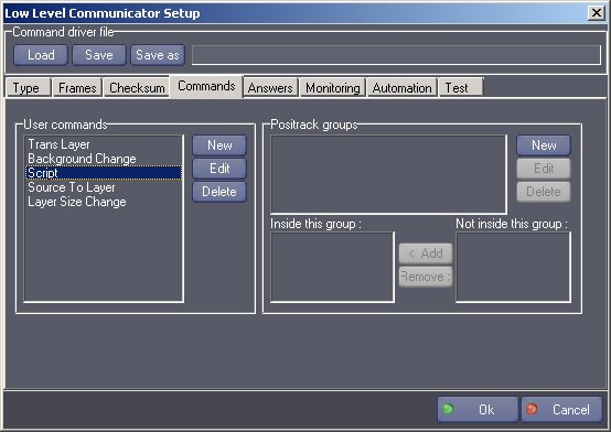
- User commands: the list of commands created.
- Positrack groups: the list of all the groups created.
- Inside this group: the list of commands that belong to the group selected.
- Not inside this group: the list of commands that do not belong to the group selected. When you create a new command, tou can specify the name and the output frame of this command.
In the output frame, it is possible to define parameters, that will appear afterwards in the “Send User Command” command.
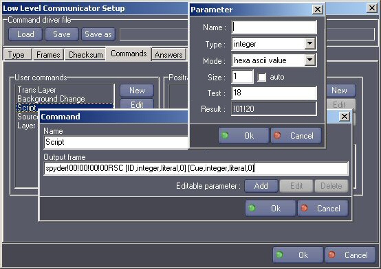
In the frame, the syntax of the parameters are between brackets. It contains the name, the type, and the size of the parameter.
Six types of parameters can be specified:
- integer
- string
- time
- date
- enum
- real
This option defines the type of the parameters that will appear in the command cue. Depending on the ‘Mode’ option, the parameter will be interpreted differently (see below).
Six modes of conversion can be specified:
- ‘hexa ascii value’: the resulting bytes in the frame will be the ascii representation of the hexadecimal value of the parameter. The value of the parameter is first converted in an integer, then the hexadecimal value of this integer is converted in ascii (a value of 35 (!23) will generate the bytes !32 and !33). In the case of Real, the value is first rounded to an integer.
- ‘decimal ascii value’: the resulting bytes in the frame will be the ascii representation of the decimal value of the parameter. The value of the parameter is first converted in an integer, then this integer is converted in ascii (a value of 35 will generate the bytes !33 and !35). In the case of Real, the value is first rounded to an integer.
- ‘bcd value’: the resulting bytes in the frame will be the ascii representation of the binary-coded-decimal value of the parameter. The value of the parameter is first converted in an integer, then each power of 10 of this value is converted in bcd (a value of 125 will generate the bytes !01 and !25). In the case of Real, the value is first rounded to an integer.
- ‘low-high bytes’: the resulting bytes in the frame will be the binary value of the parameter, with the low byte first. The value of the parameter is first converted in an integer, then the resulting bytes are organized low bytes first (a value of 14387 (!38!33) will generate the bytes !33 and !38). In the case of Real, if the size is set to 4 or 8, the real value is converted in float or double binary representation, in little endian, any other size (including auto) will result is 0 values.
- ‘high-low bytes’: the resulting bytes in the frame will be the binary value of the parameter, with the high byte first. The value of the parameter is first converted in an integer, then the resulting bytes are organized high bytes first (a value of 14387 (!38!33) will generate the bytes !38 and !33). In the case of Real, if the size is set to 4 or 8, the real value is converted in float or double binary representation, in big endian, any other size (including auto) will result is 0 values.
- ‘literal string’: the resulting bytes in the frame will be the string value of the parameter. If the parameter is a string or an enum, the string value is keep as it is, otherwize it is converted to an integer and then expressed into a string (a value of 125 will generate the bytes !31 !32 !35 - i.e “125” ). In the case of Real, the value is first rounded to an integer.
The ‘Test’ and ‘Result’ fields can be used to check the convertion mode for the parameter. If the parameter type is string or enum, the ‘Test’ is interpreted as a string value, otherwize as an integer value.
The size represents the minimum count of bytes that will be sent: if the result of the conversion has only one byte, zero is added first.
The enum type is different than the other because for each item of the enum, you can specify tha name and the value to be sent:
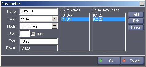
In the example above, a Power command has an enum parameter called POWER that can have 2 values: OFF and ON. When ON will be selected in the cue, the value !01!10 will be inserted in the frame. When OFF will be selected in the cue, the value !02!20 will be inserted in the frame.
Note: The name of the enum is preceded by its index.
Answers
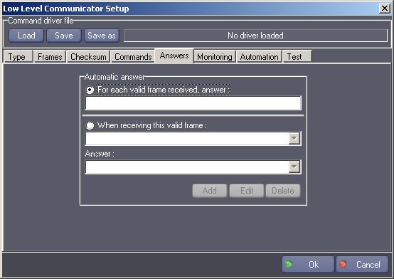
This page let you enter specific answers to frames received.
If “For each valid frame received, answer:” is checked and if a frame is specified, this frame will be sent each time any valid frame is received by this device.
if “When receiving this valid frame” is checked, you can specify a list of answers corresponding to a list of specific valid frames received.
Monitoring
In this page, you can specify a list of frames that will be periodically sent.
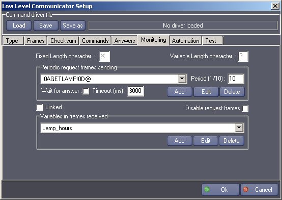
Fixed Length Character: character used in variable definition to specify a fixed length unknown character (default is ‘X’).
Variable Length Character: character used in variable definition to specify a variable length character string (default is ‘?’).
Period: The period if the time in tenth of seconds at which the selected request is sent. Each request can have a different period.
Wait & timeout: If the “Wait for answer” is checked, the device will wait from an answer before another request is sent. If the answer is not received within the time specified in the “Timeout” parameter, the next request is sent.
You can also create monitor variables.
These variables will appear in the Variables Inspector of Manager and will be automatically updated each thier corresponding frame is received.
Linked: A request can be linked to a monitoring variable. It means that the frame containing the variable will be considered as valid only if the linked request has been sent just before. If the protocol that you use does not send the same answer format for several monitoring variables, you don’t need to use the “link” mode.
Disable request frames: This is useful when you are in test phase: it disables the periodic sending of the request frames.

After entering the name and the type of variable, enter the waited frame.
Use the fixed length character (default is ‘X’) to specify undefined characters.
Use the variable length character (default is ‘?’) to specify a undefined string of character.
To determinate the position and the length of the bytes to be monitored in the variable, select these bytes in the frame before closing the dialog box.
- Type: The types can be:
- Integer
- String
- Time
- Date
- Enum
When the type is integer or time, the variable is updated with the binary value of the bytes received.
When the type is string or date, the variable is updated with the literal value of the bytes received.
If the selected type is Enum the dialog box shows an enum editor which allows to define the Enum.
Format
hexa ascci value: the bytes received are the ascii representation of the hexadecimal value.
decimal ascii value: the bytes received are the ascii representation of the decimal value.
bcd value: the bytes received are the binary coded decimal representation of the value.
low-high bytes: the bytes received are binary bytes,with low byte first.
high-low bytes: the bytes received are binary bytes, with high byte first.
Update Mode:
Immediate: The variable is updated when the frame is received regardeless if the ‘Store Frame’ option is checked.
On ‘Get last frame’ Command: The variable is updated when the frame is read with the command ‘Get last frame’. If there are some other frames already stored in the input buffer, those frames must be read before the variable could be updated.
Note: if the option ‘Store Frames’ is not checked in the Frames tab, this option has no effect and the default ‘Immediate’ mode is used.
Note: when the value type is ‘Integer’, it is possible to display the value in decimal or integer format in the dialog box that opens when editing the value.
Examples:
if the variable type is integer with format “high-low bytes” and the frame specified is VALUE=X (where X is selected) and the frame received if VALUE=!02, the value of the integer variable will be 2.
if the variable type is integer with format “high-low bytes” and the frame specified is VALUE=XX (where XX is selected) and the frame received if VALUE=!01!02, the value of the integer variable will be 258 ( 102 in hexadecimal).
if the variable type is string with format “high-low bytes” and the frame specified is VALUE=X (where X is selected) and the frame received if VALUE=2, the value of the string variable will be “2”.
if the variable type is string with format “high-low bytes” and the frame specified is VALUE=X (where X is selected) and the frame received if VALUE=!02, the value of the string variable will not be a displayable character because !02 is not a valid ASCII character.
if the variable type is integer with format “high-low bytes” and the frame specified is VALUE=X (where X is selected) and the frame received if VALUE=2, the value of the integer variable will be 50 ( 50 is the decimal ASCII value of “2”, 50=32 in hexadecimal ).
if the variable type is integer with format “high-low bytes” and the frame specified is VALUE=XX (where XX is selected) and the frame received if VALUE=12, the value of the integer variable will be 12594 ( 3132 in hexadecimal, where 31 is the hexadecimal ASCII value of “1”, and 32 is the hexadecimal ASCII value of “2”).
if the variable type is integer with format “bcd value ” and the frame specified is VALUE=XX (where XX is selected) and the frame received if VALUE=!01!23, the value of the integer variable will be 123.
if the variable type is integer with format “hexa ascii value ” and the frame specified is VALUE=X (where X is selected) and the frame received if VALUE=A, the value of the integer variable will be 10.
if the variable type is integer with format “decimal ascii value ” and the frame specified is VALUE=XX (where XX is selected) and the frame received if VALUE=14, the value of the integer variable will be 14.
if the variable type is String with the Litteral String format and the frame specified is “Status=?!0D” (where ‘?’ is selected) and the frame received is “Status=Playing!0D”, then the value of variable will be “Playing”.
If the frame received is “Status=Paused!0D” then the value of the variable will be “Paused”.
Enum Definitions Remark:
When the parameter type is an enum, an enumeration list defines the different value the enum can take. The name defines the name of the enum and is preceded by its index. The data value defines the actual data which has to be detected within the frame to select this particular enum value.
Avanced Monitoring Variable Setup:
Clicking on the “Advanced” button of the Monitoring Variable Setup Dialog allows setting Bit Mask parameters.
The Bit Mask parameters are useful when the monitoring value embeds information in particular bits. A Bit Mask can only be applied to integer or integer enum values.
Available options are:
No Bit Mask: no special bit mask processing is done on the monitoring value
Use Bit: the monitoring value is equal to the value of the specified bit. The value is ‘1’ if the specified bit is set.The value is ‘0’ if the specified bit is not set. For example, if the value is ‘36’ ( ‘24’ in hexadecimal format or ‘00100100’ in binary format) and the specified bit is bit #2, the value of the monitoring variable will be ‘1’ because bit #2 is set. Note that bit numbers are zero based. Bit #0 is the rightmost bit in binary form.
Use Bit Range: the monitoring value is equal to the value of the specified bit range shifted to the right by the specified ‘Shifted By’ value.
For example, if the value is ‘36’ ( ‘24’ in hexadecimal format or ‘00100100’ in binary format) and the specified bit range is from bit #2 to bit #5 shifted by 2, the value of the monitoring variable will be ‘9’ (‘00001001’ in binary format).
The Bit Mask processing is done after the format conversion (‘Hexa ascii value’, ‘High-Low bytes’, etc.) is applied.
Automation
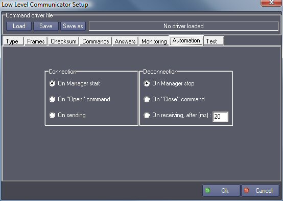
This page tells when the device will make the connection (for example the opening of the port for a serial device).
On Manager start: the connection is done when Manager enters run or debug mode.
On “Open” command: the connection is done only when the command “Open” is called.
On sending: the connection is done just before sending a frame.
On Manager stop: the disconnection is done when Manager enters stop mode.
On “Close” command: the disconnection is done only when the command “Close” is called.
On receiving after xx ms: the disconnection is done xx milliseconds after receiving a valid frame.
Drivers

The drivers can be saved into ascii files. These files have the INI format and can be edited by double-clicking on them.
They are located in the “Low Level Communicator Drivers” directory of the MxMs folder of Manager.
These drivers are used to store the parameters in another place than the Manager project, so that they can be easily re-used and exchanged.
After the setup of the device is done, the driver file is no more used since the parameters are saved also in the Manager project.
If a driver has been previously loaded from a file and the parameters of this driver have been modified, the modifications are automatically saved in the original file. However the changes are not automatically applied to other devices of the project which use the same driver. In order to apply the modifications, the driver file must be manually loaded in each of these devices.
Note that Low Level Communicator Drivers can also be downloaded from the Medialon WEB site http://www.medialon.com/download/ktor_drivers/.
Test
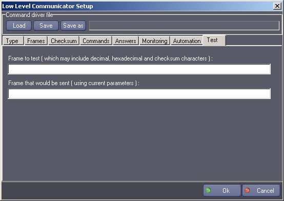
In this window, you can test the frames. In can be useful for verifying a checksum, for example The format of the frame that would be sent takes in account all the parameters of the other pages.
Device Commands
Some commands are available only for specified types. The types are written into brackets besides the command.
User commands defined in the device setup are added to this command set.
Open
(all types)
Open the communication.
Usage: This command can be called if the opening of the communication is not set to automatic in the setup of the device.
Close
(all types)
Close the communication.
Usage: This command can be called if the closing of the communication is not set to automatic in the setup of the device.
Sendframe
(Serial, TCP/Client, MIDI,TCP/IP Server, UDP/IP Client-Server )
Send the specified frame.
- Output frame [String] The frame to send.
Usage: In TCP/IP server mode the frame is sent to all of the connected clients. In UDP/IP Client-Server mode, the frame is send to the default destination address and port.
Send frame to
(TCP/IP Server) (TCP/Server is not available in lite version )
Send the specified frame to a client.
- Output frame [String] The frame to send.
- Address [String] Address of the client connected to send to. Several client addresses (separated by a comma, space, dot, line feed or carriage return) can be specified. The “ClientsList” device system variable can be used as the address.
Send frame to
(UDP/IP Client-Server)
Send the specified frame to a client.
- Output frame [String] The frame to send.
- Address [String] Address of the computer to send to.
- Port [Integer] Port of the computer to send to.
Get last frame
(Serial, TCP/Client, MIDI)
Read a frame from the next incoming frame buffer list.
- Input frame [String] The string that will be filled with the incoming frame in return.
Usage: This command must be called when the variable FramesCount (see below) becomes not null. This variable indicates the count of incoming frames waiting to be read.
Each time a frame is read with this command, the variable FramesCount is decreased by one and the frame read is punched out of the buffer list.
Get frame
(TCP/IP Server, UDP/IP Server) ( TCP/Server is not available in lite version )
Read a frame from the next incoming frame buffer list.
- Input frame [String] The string that will be filled with the incoming frame in return.
- Client address [String] The address of the computer that has sent the frame.
Usage: This command must be called when the variable FramesCount (see below) becomes not null. This variable indicates the count of incoming frames waiting to be read.
Each time a frame is read with this command, the variable FramesCount is decreased by one and the frame read is punched out of the buffer list. The addresses can be retrieved in the ClientsList variable.
Get byte
(all types)
Read a byte from the last incoming frame.
- Return ascii value [String] The string that will be filled with the byte value (see usage)
- Byte index [Integer] The index of the byte in the frame
Usage: This command can be called when the variable FramesCount is not null. When a byte is read with this command, the variable FramesCount is NOT decreased by one and the frame remains in the list (see command above: “Get Frame” for punching out the frame).
The Return ascii value can contain an hexadecimal representation of the byte, if it is not litteral, like it has been set in the setup of the device for the sending of hexadecimal character ( for example !0D )
Change count of bytes
(all types)
Change the count of byte that the device is waiting for (incoming count of bytes).
- Count of bytes [Integer] New count of bytes.
Usage: In many protocols, the count of by of the responding frames depends of the type of command frame sent. This is the purpose of this command.
Set DTR
(serial)
Change the DTR signal.
- DTR value [Integer] New value (0 or 1).
Set RTS
(serial)
Change the RTS signal.
- RTS value [Integer] New value (0 or 1).
Get client name
(TCP/IP Server) ( TCP/Server is not available in lite version )
Return the name of the specified client.
- Address [String] Address of the client.
- Return name [String] The string that will contain the address in return.
Change IP parameters (NOT AVAILABLE ON SHOWMASTER MINI)
(TCP/IP Client, TCP/IP Server, UDP/IP Server) (TCP/Server is not available in lite version)
Set new IP parameters for this device.
- Address [String] New address.
- Port [Integer] New port.
Device Variables
Only the default variables are listed here. New variables can be created in the Monitoring page of the setup dialog.
Status
[Enum] Status of the connection.
- Closed: the connection is closed.
- Opened: the connection is opened.
- Error: no connection due to an error.
- Adapter Address Error: The specified adapter address for reception is not present in this machine.
LastCommandStatus
[Enum] Status of the current command.
- Success: the command has been succesfully executed.
- Pending: the command is currently executed.
- Error: the command could not be executed.
Frames count
[Integer] Count of incoming frames.
Usage: This variable indicates the count of incoming frames waiting to be read.
Each time a frame is read with the command “Read frame”, the variable FramesCount is decreased by one and the frame read is punched out of the buffer list.
Input bytes count
[Integer] Count of incoming bytes of the current frame.
Usage: This variable indicates the count of incoming bytes that are filling the current frame. If there are several frames in the queue, it does not represent the total of bytes of all the frames, but only the count of bytes of the last frame received. It can be useful when the parameters “count of bytes” and “timeout” are set to zero in the setup of the device with a protocole with variable length frame.
Last received frame
[String] The last frame received on input.
Usage: You can use this variable for reading the input frames, but be aware that if the frames arrive too fast, the variable can be overwritten by the next frame, while you read it (if it is the case, use “Keep all the input frames in memory” and the “Get Frame” command).
Clients count
[Integer] Count of connected clients (in TCP/IP Server mode).
Clients list
[String] List of connected clients.
DSR status
[Integer] Current DSR status (serial device).
CTS status
[Integer] Current CTS status (serial device).
Revisions
V 1.0.1
- Bug Fixed: crash if a negative value is used as an index of an enum parameters in a user command.
V 1.0.2
- Added: Support for Showmaster.
V 1.0.3
- Corrected: Button font color corrected in the setup dialog.
- Modified: “Automation/On project load” and “Automation/On project unload” options have been removed from the setup dialog.
- Corrected: The value was not returned by “Get Last Frame” if the return variable was not a string type.
- Corrected: The value was not returned by “Get Byte” if the return variable was not a string type.
- Corrected: When “Get Byte” was called, the expected count of byte was changed in the setup.
- Fixed: False error detected when loading a project with deleted (strikethrough) cues. This bug fix requires Manager 5.0.2 or higher.
- Fixed: Crash when sending a user command with a very large command frame containing user parameters.
- Fixed: The break character is not analyzed if the frame does not contain a check-sum.
V 1.0.4
- Fixed: random crash when “Get Last Frame” command is executed while receiving data.
- Fixed: Incorrect parsing of variable data from incoming frame with fixed and variable length bytes.
- Fixed: In the setup, the user can enter the same character for all the special character.
- Modified: better TCP Client Connection/Disconnection management if the specified server machine is not present.
- Fixed: user command enum variables are not created if the command frame length is greater than 4Ko.
- Fixed: user command frames are truncated when read from the driver file if the command frame length is greater than 2Ko.
V 1.0.5
- Fixed: impossible to specify the address and the port to which the monitoring udp frames are periodically sent (fixed by adding default destination parameters).
- Improvement: “Send Frame” can be used in UDP Client-Server mode (with the default destination parameters specified in the setup).
- Improvement: When the setup of a device using a driver is changed, the user is offered three possibilities of saving ( device only, device and driver, new deriver ).
- Fixed: Incorrect parsing of variable data from incoming frame with fixed and variable length fields when the variable monitoring frame segment also contains regular (non wildcard) characters.
V 1.0.6
- Fixed: In the setup, adding a parameter at the start of a command deletes the whole frame.
- Fixed: the command text is not computed if it starts by the bracket of a parameter description.
V 1.0.7
- Fixed: Incorrect parsing of variable data from incoming frame with fixed and variable length fields when there are one or more fixed length fields after the last variable length field.
- Added: Support for Showmaster Pro.
V 1.0.8
- Added: Monitoring Variable bit mask processing.
V 1.0.9
- Fixed: Inner values of IP Address containing leading zero are converted from octal values instead of decimal.
V 1.0.10
- Fixed: Default UDP parameters are not used in User Commands and ‘Send Frame To’ command (UDP mode).
V 1.2.0
- Fixed: Cannot create more than 255 LowLevelCommunicator devices.
V 1.2.1
- Fixed: a parameter of a driver command is not processed if it is larger than 2048 bytes.
V 1.2.2
- Fixed: Incorrect parsing of variable data from incoming frame with variable length field when the variable length field is at the end of the frame.
V 1.2.3
- Fixed: Incorrect parsing of variable data from incoming frame with variable length field. Fixes a bug introduced by the previous version.
V 6.0.0
- Modified: Support of Manager V6/Showmaster V2.
V 6.0.1
- Fixed: Setup dialog doesn’t open on the correct screen on a multi-screen configuration.
V 6.0.2
- Fixed: Driver command enum values are incorrectly processed.
V 6.0.3
- Fixed: Device’s variables are not reset after a project load (Requires Manager 6.0.3+).
- Fixed: Issues while editing user commands under Showmaster Editor V2 (“Delete” button disabled in the setup dialog, Existing cues red-crossed after commands have been edited).
- Modified: Internal changes.
V 6.1.0
- Added: Support for CRC8 ‘checksum’ computation mode.
- Added: TCP/IP Server mode behavior notes.
V 6.1.1
- Fixed: Low Traces do not work.
- Added: Support for Showmaster LE & Showmaster XS platforms.
- Added: Usage information within Showmaster Platforms.
V 6.1.2
- Fixed: A project cannot be reloaded after it has been saved with deleted user commands.
- Fixed: A memory leak occurs when variables are used with user commands.
- Fixed: A device using checksum verification on input frames makes Manager/Showmaster to hang if the checksum is incorrect.
- Added: Test and Result field in user command’s parameter editor.
- Added: Information on how does work integer conversion in user command’s parameter in this help.
- Fixed: FramesCount counter is not updated properly is come circumstances; in that case, the value doesn’t reflect actual pending frame count.
- Changed: Hexadecimal value representation has been uniformized in this document.
V 6.1.3
- Fixed: Enum values are not updated in existing cues when an LLC command enum parameter is modified in the setup dialog.
V 6.1.4:
- Fixed: Terminating space characters of command frames are not saved in driver files.
- Fixed: Misspelling in setup dialog box.
V 6.1.5:
- Fixed: Serial resource is not released when the device Type is changed.
- Fixed: The commands list from a custom driver is not displayed in its definition order in Manager/Editor.
- Fixed: The Setup dialog box is not always fully visible at the device creation time.
- Fixed: Some dialog boxes can be opened outside of the screen at the device creation time.
V 6.1.6
- Fixed: Parameters dialog boxes don’t display properly if the text magnifying settings (DPI) is greater than 100% into Windows system.
V 6.1.7
- Fixed: “Count of bytes” of the Setup “Input frame” parameter is incorrectly reset to 0 when the device is stopped.
V 6.1.8
- Fixed: The description and settings of enum values is not clear (index versus data value).
V 6.2.0
- Fixed/Improved: Keep Alive option has been added for TCP Client and TCP Server modes to manage dead half open connections.
- Fixed: Random crash when sending user commands while running under a heavy loaded multicore environment.
V 6.3.0
- Fixed: A space character at the end of a Monitor Variable value is not properly read when a driver is loaded.
- Added: Support for real parameter in user commands.
V 6.3.1:
- Fixed: LastFrame variable content is saved into the project even if the variable is not persistent in the host (require Manager 6.5.0+).
V 6.4.0:
- Added: Compatibility for Overture CS.
- Improved: Optimized for Overture CS.
V 6.4.1:
- Fixed: Manager or Showmaster Editor may crash when switching a device from a communication type to another (for instance from TCP Client to UDP).
- Fixed: When the device communication type was changed, most of the standard commands were deleted
- Fixed: Monitor variables with same pattern are all updated when a frame is received after an automatic request command has been sent for one of them. This occurs even when the option Wait Answer is set
- Fixed: The Delete button for a command stays grayed when used inside Overture CS
- Fixed: On the command creation dialog, it is possible to validate a command even when the name field is empty
- Fixed: UDP Default Destination Parameters are not saved into drivers
- Fixed: When some parameters such as destination parameter in UDP are changed, the option dialog to chose where to save the changes is not displayed
- Fixed: Cannot setup a device which has been created after more than 256 devices have already been created in the project
- Fixed: User command enum parameters are corrupted after edit if enum names contain parenthesis character.
V 6.4.2:
- Fixed: Starting a UDP multicast device cause the device to block in pending on some machines.
V 6.4.3:
- Added: A TCP Client has a new option named “Deconnection on Timeout” allowing to detect when troubles happen on the network. For example if the Ethernet cable is unplugged from the device to control, the MXM device is not notified that the connection is supposed to be closed. This option provides a way to detect that the device is not responding anymore.
V 6.7.0:
- Improved: Support for High DPI displays (require Manager 6.7.0+ or Showmaster Editor 2.7.0+)
- Changed: Compatibility for Manager 6.7.0 and Showmaster Editor 2.7.0
V 6.7.1:
- Fixed: Sometimes the processed checksum is not correct.
- Improved: A new option has been added in the “Frame” tab allowing to define the “Max stored frames” when the “Store frames” is enabled.