| Name: | Medialon IO |
| Version: | 6.7.2 |
| Available for: | Manager V7 and Manager V6 (Lite & Pro), Showmaster (Mini, ST, Pro, LE, XS & iPro) |
| Limitation In: | |
| Device Brand: | Medialon |
| Positrack Compatible: | Yes |
| Ressources type: | I/O |
Overview
This MXM allows controlling and monitoring various types of Inputs/Outputs (I/Os) with a unified programming and user interface.
The I/O resources themselves are provided by MRCs (Medialon Resource Connectors) which implement I/O Resource management like the “Advantech ADAM” MRC. This MxM requires Manager V4.10 or higher.
MxM Installation
This MxM doesn’t require any specific installation but I/O resources used by a Medialon I/O device must be properly declared and configured prior creating a device. See the Manager User’s Manual for more information about resource configuration.
Device Setup
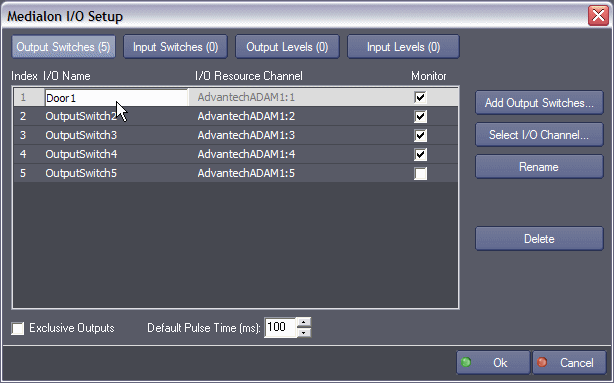
Device setup window:

The device setup window allows declaring and configuring the device I/O channels.
I/O channels can be one of the following types:
- Output Switches (digital outputs)
- Input Switches (digital inputs)
- Output Levels (analog outputs)
- Input Levels (analog inputs)
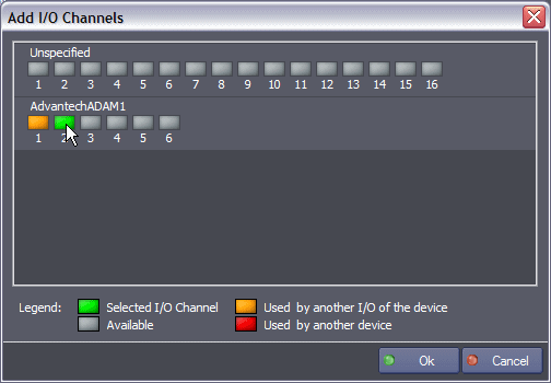
To add an Output Switch (digital output channel) to the device, click on the “Output Switches” button at the upper left of the setup window in order to show the currently configured output switches. Then click on the “Add Output Switches…” button. This displays the “Add I/O Channels” dialog box as shown bellow. The procedure is the same for other type of I/O.
Adding I/O channels to the device

Select one or several available I/O channels by clicking on the corresponding button and click the “Ok” button. Note that clicking on an already selected channel deselects this channel. “Unspecified” channels may also be added to the device in case the final I/O configuration is not known at programming time.
Configuring an I/O channel

To rename an I/O channel either select a channel and click on the “Rename” button or double click on the I/O channel name. Type the name and press enter or click elsewhere. Note that a channel name must be unique in the scope of the device.
I/O channel monitoring can be turned on or off by checking the “Monitor” check box of the relevant I/O channels.
A system monitoring variable is created for each monitored channel.
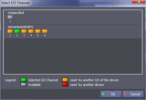
The I/O resource attached to a device I/O channel can be modified after creation time by selecting an I/O channel and clicking on the “Select I/O channel” button or by double-clicking on the “I/O resource channel” column. This displays the “Select I/O Channel” dialog box which is similar to the “Add I/O Channels…” dialog box.

Note that a I/O channel can be set to “Unspecifed” by clicking on the “Unspecified” channel pin A channel can also be deleted by selecting the channel and clicking the “Delete” button.
Specific Output Switch configuration
Specific device output switches configuration is available on the “Output Switches” page.

- Exclusive Outputs: Enables the device to force only one closed output switch at a time.
- Default pulse duration: Specifies the value of a switch pulse (sequence on/off) used by default if no other value is chosen in the “Set Switch Status” command.
Device Commands
Set Switches Status
Set the status of one switch output.
- Select By: [Enum] Switch selection method.
- “Name”: select switch by its name.
- “Index”: select switch by its index (in the device). Valid indexes start at 1.
- Name: [String] Name of the switch (Select By should indicate Name).
- Index: [Integer] Index of the switch (Select By should indicate Index). Index 0 means all switches of the device.
- Status: [Enum] Status to set to the output.
- “Off”.
- “On”.
- “Pulse”: generate a sequence On/Off with the specified duration.
- “Toggle”: Invert the current status.
- Pulse Duration: [Time] Duration of the pulse (if selected as status). If this value is 0, default pulse duration is used.
Switches Memory
This command sends a switches memory as they have been programmed by insertion of a switches memory Cue in the task.
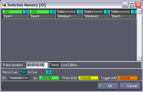
For the creation of the cue, a dialog box appears:

Status of each switch could be changed by clicking on it. Different statuses are display using different symbols (see symbols table area).
A switch is defined by 3 areas:
- Status itself (Off, On, Pulse, Toggle).
- In Cue/Not in Cue consideration.
- Name.
Memory example description:
- switch 0:000:04 is in Cue (in memory) and its state is off
- switch 0:000:05 is in Cue (in memory) and its state is on
- switch 0:000:06 is in Cue (in memory) and its state is pulse (selected pulse duration is 00:00:01/00).
- switch 0:000:07 is in Cue (in memory) and its state is toggle
- switch 0:000:08 is NOT in Cue (in memory) and its state does not matter, this switch will not be updated by the memory.
Pulse duration
Indicate the pulse duration for all switches with status set to Pulse (Yellow symbol). If this value is 0, the default pulse duration is used.
Live Edition
Enable or not to update switch status in real time (like memory is).
Symbols area
Explains the signification of each symbols used in switch status display area.
Read Switch Status
Read the current status of one switch output or input into the given variable.
- Select By: [Enum] Switch selection method.
- “Name”: select switch by its name.
- “Index”: select switch by its index (in the device).
- Name: [String] Name of the switch (Select By should indicate Name).
- Index: [Integer] Index of the switch (Select By should indicate Index).
- Type: [Enum] Type of switch.
- “Output”.
- “Input”.
- Status: [Integer] Current status of the given switch.
This parameter is an outgoing value, it is set when the command execution finished.
Set Level Status
Set the status of one output level.
- Select By: [Enum] Output level selection method
- “Name”: select output level by its name.
- “Index”: select output level by its index (in the device). Valid indexes start at 1.
- Name: [String] Name of the output level (Select By should indicate Name).
- Index: [Integer] Index of the output level (Select By should indicate Index).
- Status: [Real] Level to set (0% to 100%).
Levels Memory
This command sends a levels memory as they have been programmed by insertion of a levels memory Cue in the task. This option works in a quite similar way than the “Switches Memory” function.

Read Level Status
Read the current status of one level output or input into the given variable.
- Select By: [Enum] Switch selection method.
- “Name”: select level by its name.
- “Index”: select level by its index (in the device).
- Name: [String] Name of the level (Select By should indicate Name).
- Index: [Integer] Index of the level (Select By should indicate Index).
- Type: [Enum] Type of level.
- “Output”.
- “Input”.
- Status: [Real] Current status of the given level.
This parameter is an outgoing value, it is set when the command execution finished.
Device Variables
Status
[Enum] Current status of the device connection.
- “Unconnected”: Not connected
- “Connecting”: Connection in progress
- “Ready”: Device is connected and ready to work
- “Open Error”: Open Error
ResourceStatus
[String] Current status of the resource(s) used by the device.
I/O monitoring variables
Variable names are composed by the device name and the IO name.
[Integer] or [Real].
Current output or input state of the IO.
Usage: When IO is a switch, the variable is an Integer variable whose value is 0 or 1 (1 when the input is detected, 0 otherwise). When the IO is an output or an input level, the variable is a Real variable which ranges from 0% to 100%. The precision (number of digits) of the variable can be set in variable properties.
Revisions
V 1.0.1
- Added: Support for Showmaster.
V 1.0.2
- Fixed: cue channel name parameter wizard doesn’t work anymore after the device has been modified by the Setup Dialog.
V 1.0.3
- Fixed: crash when adding I/O channels in the device setup dialog with Manager 5.0.3 or higher. Note that this version of the MxM is not compatible with Manager versions below 5.0.3
- Fixed: in the setup, the refreshing of the IO list is very slow when there is a lot of IOs.
- Fixed: in case of error the status of the device is not updated.
V 1.0.4
- Fixed: clicking on the “Select I/O Channel…” button has no effect
- Fixed: crash when closing the setup dialog while a I/O name editing is in progress
- Added: Support for Showmaster Pro.
V 1.0.5
- Fixed: import corrupts I/O channel settings
- Fixed: I/O channels are now labeled starting from “1” in the setup dialog
V 1.0.6
- Fixed: inputs are still active when the device is disabled.
V 1.0.7
- Added: Manager Kiosk compatibility.
V 6.0.0
- Modified: Support of Manager V6/Showmaster V2.
V 6.0.1
- Fixed: Setup dialog doesn’t open on the correct screen on a multi-screen configuration.
V 6.0.2
- Fixed: Manager Kiosk compatibility doesn’t work.
V 6.0.3
- Fixed: Cannot edit “Switches Memory” cues after a project is loaded.
- Fixed: Device variables are not reset after a project load (Requires Manager 6.0.3+).
- Fixed: Digital device’s variables are not limited to 0/1 values.
V 6.1.0
- Added: Support for Showmaster LE & Showmaster XS platforms.
V 6.1.1
- Fixed: The MXM does not appear as certified under Manager.
V 6.1.2
- Fixed: The Setup dialog box is not always visible at the device creation time.
V 6.1.3
- Fixed: The Cue window and the ControlPanel don’t display the Switch/Level values properly if the text magnifying settings (DPI) is greater than 100% into Windows system.
V 6.1.4
- Fixed: The I/O configuration is lost when Setup Dialog Box is closed by clicking on the upper right ‘Close’ window icon.
V 6.1.5
- Fixed: MXM Commands may sometimes hang Manager/Showmaster while the command being executed.
V 6.1.6
- Fixed: Wizard window can be displayed under the Windows taskbar.
- Fixed: Double click on the selected channel in the wizard window does not validate the selection.
V 6.1.7
- Modified: Internal Changes.
V 6.2.0
- Added: Compatibility for Overture CS.
V 6.7.0
- Improved: Support for High DPI displays (require Manager 6.7.0+ or Showmaster Editor 2.7.0+)
- Changed: Compatibility for Manager 6.7.0 and Showmaster Editor 2.7.0
- Fixed: Unloading that MXM might freeze the ShowControl software.
