| Name: | BSS Soundweb London |
| Version: | 6.7.2 |
| Available for: | Manager V7 and Manager V6 (Lite & Pro), Showmaster (Mini, ST, Pro, LE, XS & iPro) |
| Limitation In: | |
| Device Brand: | BSS Audio |
| Positrack Compatible: | No |
| Resources type: | TCP/IP Network, Serial |
Overview


This MXM allows to control and monitor the three types of Soundweb London devices: BLU–16, BLU–32 and BLU–80.
Each MXM instance can control one London device, either via a serial/COM connection or via Ethernet/TCP/IP. A serial link between the PC running Manager and the London device is required when operating in serial mode. For the Ethernet mode, any connection scheme will work as long as the London device and the PC running Manager can “see” each other on the network.
The hardware configuration and internal patch creation, loading and saving are done by using the BSS London Architect PC application. This MXM does not allow building DSP graphs from scratch and thus does not intend to replace or supersede the London Architect software.
By using this MXM, one can control and monitor the state of any built-in or custom DSP object inside the London’s internal DSP graph.
Built-in objects correspond to the common controls found in each London unit (like the input gains and meters) and are created automatically when completing the MXM device setup.
Custom objects are created to match any object / state variable inside the DSP graph (like EQ’s, compressors etc…) Note that the BLU–32 device does not have any internal DSP processing power, and thus does not allow creating custom objects.
After having completed the setup and configuration steps on both London Architect and Manager’s sides, you will ve able to send control change messages to the device, recall parameter and device presets, and monitor the status of any state variable or VU-meter.
MxM Installation
Please refer to the device manual for wiring and setup instructions. The London Architect PC software will also be required in order to build and configure the device(s). Please note that the Architect software can be installed on any PC, not necessarily the one running the Show Control software.
Important read carefully: the London product range being quite new when this MXM was first released, there are some known limitations due to features of the London control protocol being not implemented in the old firmware versions. In fact, many features won’t work at all with the original firmware shipped with the devices. Please, always download and install the latest London firmware from the BSS website before attempting to use this MXM. Refer to the London user manual for the firmware updating process.
Known limitations: when using the MxM in Serial/COM mode, be aware that there is no probing mechanism implemented. So if the connection is broken or the device down, this won’t be reflected by the “connection status” system variable, but serial errors will occur and be catched by the “error” system variable. This problem does not appear when using the Ethernet connection mode
Legal notice: Soundweb, Soundweb London, the BSS logo and the London Architect software are all trademarks or properties of BSS Audio, a Harman Music Group company.
Device Setup
In order to use the London MXM, you must take the following configuration and setup steps: The first part is done on the Architect side, where you must create the internal patch and routing as explained in the user manual. Once finished, you must upload you patch inside the London device by going online with Architect. A prompt will ask you if you want to update the London device(s)
When all your logical “soft” setup are completed, keep your Architect instance running as we are going to need it again during the next steps.
Create an instance of the London MXM using the device manager. This will show the device setup dialog.
Step 1:
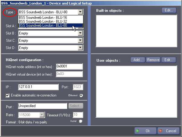
First of all, you must select the correct hardware type you are going to control, i.e. the type of your London unit.
This information is used by the MXM to guess the available capacities of your hardware (since BLU–16, BLU–32 and BLU–80 are all different)
Step 2:
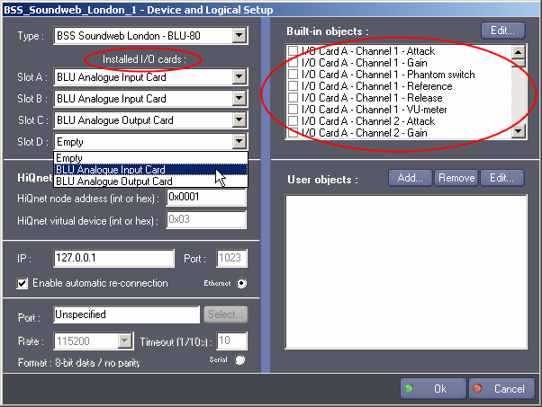 Select (if available) the correct I/O cards installed in your London unit. Theses cards are selected only once since they should not change too often.
Note that the corresponding built-in objects are automatically created for you on the right pane. These objects match the default controls available for each I/O card and allow for a quicker control selection when creating cues.
We will study how to use the built-in and custom objects in the next steps.
Step 3 and 4:
Now open the London Architect application and display the “network” pane as shown in the following figure.

Select the London unit you want to control with this MXM instance, and retrieve its HiQnet node address. Please note however that HiQnet nodes are assigned at runtime, hence the London unit must be powered and connected to Architect if you want to retrieve the correct address.

Then report this node address inside the MXM setup dialog. Please note that the hexa value will be internally converted to a decimal one by the MXM, so you can also directly enter a decimal value, even if this is less convenient.
The HiQnet virtual device is always 0x03 for all audio devices on the network. You can’t change this value in the actual implementation.
Step 5:
You now have to choose between a serial/COM and an Ethernet/TCP/IP connection to the device. A single connection scheme can be used at a given time, using both COM and ETH together is not supported. To switch between modes, you just have to click the correct radio-button.
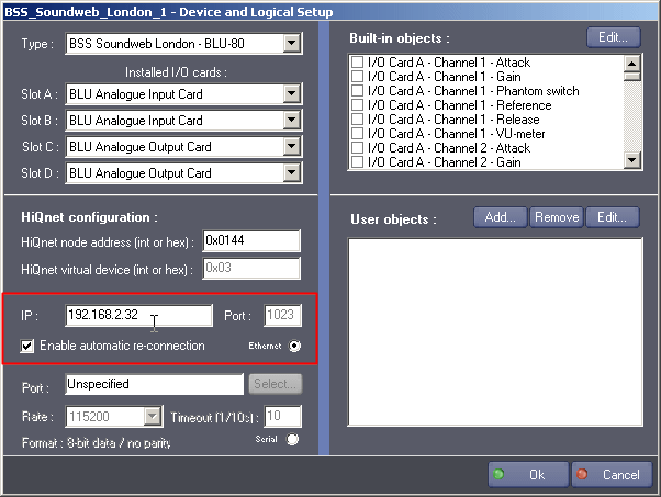
When using the Ethernet mode, you must provide the MXM with the IP address (or hostname) of the London device on the local area network. Ensure that no firewall or router is blocking traffic on the required port (1023) The communication port is fixed by the London control protocol, it is given here only as a convenience.
When checked, the “Enable automatic re-connection” option allows to automatically re-open the TCP/IP connection when it is disrupted. When it is not checked, manual re-connection is needed in case of failure.

For serial/COM communication, most parameters are fixed by the protocol. You just have to select an available COM port in the drop-down combo-box. Whether a given port is used or not is shown in the port’s label.
You can also select a custom serial baudrate in the corresponding combo-box, as long as it matches the one configured in London architect. Leave this parameter as is if your are not sure.
The time-out interval is fixed at 1 second in the current implementation. When commands time-out, they are automatically resent once before giving up.
Step 6 and 7:
Built-in objects are placeholders to facilitate cues creation. They behave exactly like the custom objects, excepted that their name and HiQnet configuration are fixed.
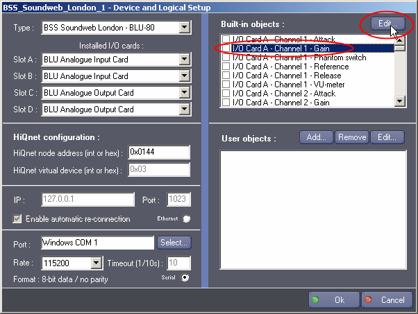
There are only two possible actions on built-in objects: monitoring their associated state variable inside the London device, and choosing between scalar values or percent values for the command data sent and received.
When monitored, a state variable is matched in Manager by a device system variable, allowing to program events based on the state variable’s value.
To monitor a state variable, select an object in the list and click the “Edit” button (alternatively, you can also double-click the object’s name) The following object edition dialog will pop-up:

If you check the “Monitor variable in Manager” checkbox, the variable will be created as soon as you apply the configuration changes (i.e. click Ok in the device setup dialog) Note: there is a faster way to select the variables to monitor. You just have to check the box placed in front of the object name in the lists without needing to go through the object setup dialog. This feature is handfull to quickly see which objects are being monitored.
State variable’s values can be of different types: integer, floating point and percent. Integer values are entered (and receveived when monitoring) as is, without any special encoding. Floating point values must be multiplied by 10000 before being converted to an integer value. The conversion can be done by hand when writing the cues, or by using the integrated cue-parameter wizard which allows to type-in human-readable floating point values.
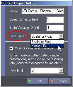
Alternatively, it is possible to specifiy a percent mode in the object edition dialog. In this mode, you can directly type-in 0–100 ranged values when creating cues, and monitored variables will also be expressed in percents. In this mode, the integrated wizard is not necessary.
Note: there is no way to know if a state variable value is expressed as an integer or a floating point number inside Architect, excepted by looking at the possible values: if the control seems to have discrete values, then it is likely to be expressed as an integer. On the other hand, if a control can take any value including fractional ones, then it is represented by a floating point number.
Step 8, 9, 10 and 11:
We will now look into the custom objects creation and edition. One creates custom object to easily control any object in the London DSP graph. Custom objects are not available for BLU–32 machines.
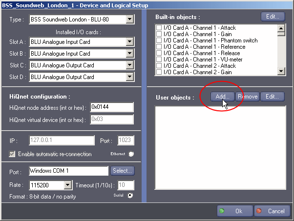
Click the “Add” button on the right pane, this will popup the object setup dialog.
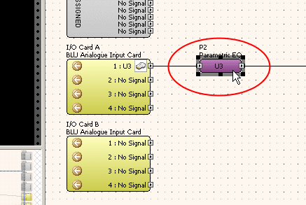
Now return to the London Architect application, and select the object which variables are to be controlled or monitored.
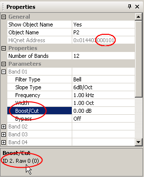
Display the object properties panel in Architect, and select the wanted state variable. State variables are found under the “Parameters” collapsible list.
Each processing object, whether it is an I/O card or a DSP object has a HiQnet object address. The object address is the last part of the full HiQnet address, as shown on the figure (it is a 24bit hexa value) In this example, the full HiQnet address is “0x014403000101” and the object address is “0x000101”. Note that each object may have any number of state variables. Each custom object on the MXM side matches one unique state variable in one processing object.
The state variable ID (decimal) is found at the bottom of the pane, and must be known too. Last but not least, the “Raw” field next to the state variable ID shows how the actual data is encoded and which value it has. It is useful to refer to these fields when programming cues.

You must now find a suitable name for the object and report all information into the object setup dialog. This information can be later modified by clicking the “Edit” button after having selected an object in the list.
Custom objects can be deleted by selecting them and clicking the “remove” button.
Final Steps:
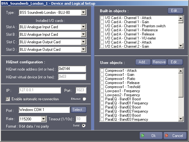
This figure shows the typical end results achieved after having successfully configured the MXM.

Note that if you later change the hardware device type to BLU–32, all custom objects will be disabled.
You can now terminate the setup process by clicking the Ok button. More custom objects can be added at any time by calling the device setup again. If you want to stop monitoring a state variable, just un-check the corresponding check-box.
Device Commands
Set Control Value
Set the value of a given state variable.
- Control Object Name: [String] Name of the target built-in or custom object, as found in the object setup dialog.
- Data: [Integer] The actual value to set. Integer values are leaved as is, but float values must be multiplied by 10000 then converted to an integer value. You can use the integrated wizard to type-in human-readable values. If the control object is in percent mode, you can directly type-in 0–100 ranged values without using the wizard.
Recall device preset
Recall a given device / venue preset by ID.
- Preset Number: [Integer] Index of the device preset. Refer to the Architect application to create and organize presets as well as to retrieve the preset ID’s.
Recall param preset
Recall a given parameter preset by ID.
- Preset Number: [Integer] Index of the parameter preset. Refer to the Architect application to create and organize presets as well as to retrieve the preset ID’s.
Send RAW Message
Same as “Set Control Value” but not using the control objects. All HiQnet ID’s must be specified by hand.
- Object ID: [Integer] HiQnet object ID converted to decimal.
- State Variable ID: [Integer] HiQnet state variable ID (decimal)
- Data Type: [Enum] Scalar/Float or Percent. Not used yet.
- Data: [Integer] The actual value to set. Integer values are left as is, but float values must be multiplied by 10000 then converted to an integer value. You can use the integrated wizard to type-in human-readable values. If the data type is percent mode, you can directly type-in 0–100 ranged values without using the wizard.
Device Variables
Status
[Enum] Current status of the device connection.
- “Unconnected”:Not connected
- “Connecting”:Connection in progress
- “Connected”:Device is connected
- “Unconnecting”:Deconnection in progress
Error
[Enum] Current error status of the device.
- “No Error”:Device is Ok
- “Network Error”:A network error occurred (Ethernet mode)
- “Command Timeout”:The last command timed-out
- “Unexpected Error”:An unexpected error occurred
- “Serial Error”:A serial error occurred (Serial mode)
Activity
[Enum] Activity LED.
- “Ready”:Device is operational
- “Busy”:A command execution is pending
- “Failure”:A serious problem occurred
- “Waiting”:Waiting for serial ACK/NAK
DevicePreset
[Integer] Actual device preset (last value recalled)
ParamPreset
[Integer] Actual parameter preset (last value recalled)
Revisions
V 1.0.1
- Added: Support for Showmaster.
V 1.0.2
- Internal Changes.
- Fixed: Serial resources can be selected while setup is in ethernet mode.
V 1.0.3
- Fixed: the wizzard of the command “set control value” does not work for selecting object names.
V 1.0.4
- Added: Support for Showmaster Pro.
V 6.0.0
- Modified: Support of Manager V6/Showmaster V2.
V 6.0.1
- Fixed: Setup dialog doesn’t open on the correct screen on a multi-screen configuration.
V 6.0.2
- Fixed: Device variables are not reset after a project load (Requires Manager 6.0.3+).
V 6.1.0
- Added: Support for Showmaster LE & Showmaster XS platforms.
V 6.1.1
- Fixed: The MXM does not appear as certified under Manager.
V 6.1.2
- Fixed: forbidden characters are allowed in Device variable names.
V 6.1.3
- Fixed: The Setup dialog box is not always fully visible at the device creation time.
- Fixed: The ‘Control Object Setup…’ dialog box can be opened outside of the screen at the device creation time.
V 6.1.4
- Fixed: The Wizard dialog boxes can be displayed outside of the screen where Manager is shown.
V 6.2.0
- Added: Support for BLU–800, BLU–805, BLU–806, BLU–320, BLU–325, BLU–326, BLU–160, BLU–120, BLU–100, BLU–101, BLU–102 and BLU–50.
V 6.3.0
- Added: Compatibility for Overture CS.
V 6.7.0
- Improved: Support for High DPI displays (require Manager 6.7.0+ or Showmaster Editor 2.7.0+)
- Changed: Compatibility for Manager 6.7.0 and Showmaster Editor 2.7.0
- Fixed: Unloading that MXM might freeze the ShowControl software.
